PID problem

Aja_AK

Member
Join Date
Dec 2015
Location
Bahrain
Posts
3
Hello
I need to use a PID controller to control the water level of a tank.
The sensor I use is a 4-20 ma sensor.
I have everything in place as the sensor has been successfully calibrated and scaled on the PLC program to give values within my 0-100 % range. However, the final (most important) piece is missing as the PID controller is currently not outputting a signal despite it seeming to work properly.
I need the output of the PID to be an analog signal in order to send it out to a microcontroller which is directly controlling the pump as per the PID controller's output.
What are the recommended PID settings to use and how do I make sure that the PID instruction is working properly?
The software I use is RSlogix 5000 with a 1769-L32E PLC.

Thanks in advance.
 
Last edited:
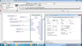
see attached file

HI Aja;

I never use PID (ladder) I use PIDE (block)instead.
In this case my level has to be 30% of tank capacity I have a controlled valve (driven by PIDE) at the input and a pump with fixed flow at the output of the tank.
You did not mention how your tank input and output are controlled.

PIDE_Level.jpg
 
Hi
My input is keyed in via a three digit thumbwheel switch, which is obviously the setpoint (SP).
The output is supposed to come from the PID block of the PLC to a microcontroller as an analog signal which will then be used to drive two pumps.
The process variable is a 0-10000 (percent range) analog sensor value (the sensor continuously measures the water level of the tank), which has been divided by 100 in order to scale the values to 0% - 100%. The result of the division is stored in an external boolean and the boolean is used as the PV in the PID block. The control variable (CV) is currently an analog output channel, and I never get a value above 0 for the CV output which means that the PID is most probably not configured correctly. DO I need to have my analog input 0-10000 directly as the PV or is alright to use a 0-100 scaled boolean?

Thanks
 
Aja: your PID is opposite to mine:
You have two pumps located at the output to control level, in my case i have a valve at the input to control level.
Your error should be E = PV - SP, mine is E = SP - PV. See my post.
That means that when level is high your pumps should handle more water in order to lower the level, in my case when level is high control valve located at the input should tend to close.
 

Similar Topics

Dear all . I made a program for boiler tank using TIA V15 , the program consists of 2 PID blocks in OB30 . but the PID didn’t work automatically...
Replies
3
Views
2,661
Dear all . I made a program for boiler tank using TIA V15 , the program consists of 2 PID blocks in OB30 . but the PID didn’t work...
Replies
1
Views
1,124
Hello Friends; I am working on a GE Funac LM 90-30 software. I face the problem to set the CV value when PID in auto mode. The parameters are set...
Replies
13
Views
3,012
I had a problem on a hydraulic servo controlled cylinder, which I believe was caused by the PID loop and the cylinder reaching a hard stop at one...
Replies
10
Views
2,443
We have a machine we're trying to commission. It's a web converting machine. It takes webs of foil, wicking paper & a label and creates a chemical...
Replies
1
Views
1,310
Back
Top Bottom