Mental Visualization of RLL / Process Flow - Help

Hester

Member
Join Date
Apr 2004
Location
Tacoma, WA
Posts
61
Bear with me as I try to articulate this problem the best I can.

I struggle with RLL. Frankly when I look at Ladder Logic sometimes, with complex flows, it rears up in my face as pure gobbly-gook. It mind as well be japanese.

I'm a person who learns best by visual input, and I am trying to find a way that I can visualize in my mind what the abstract RLL is actually doing and convert it into mental visualizations which will allow me to navigate the states of the individual devices, relays, etc into a usable mental picture.

What tricks or mental things do you guys do to understand rapidly what a flow diagram is doing???

Sincerely,

Your's Truly, It's never been a piece of cake for me.
 
Not sure whether it is RLL or flow diagrams (or both) that is the problem for you.

Actually I dont like flow diagrams to represent an automation project.
Flow diagrams seems to be a (bad) cross between state diagrams and representation of continous proces data.

I use state diagrams a lot. To view RLL code that executes states can be difficult. You need the state diagram on a piece of paper. Even if you dont have the state diagram, you can recreate it from the RLL code.
Then it shall all be clear to you :nodi:
 
... notes from a formerly frustrated individual ...

Greetings Hester,

you said:
... with complex flows, it rears up in my face as pure gobbly-gook ...

if understanding “what happens first – what happens next” is the root of your problem, maybe this trick will help (at least for RSLogix projects) ...

first put the rung in the edit mode ... then double-click the rung number until the “ASCII edit” window appears ... this shows the contents of the rung as a text string something like this:

BST XIC I:2.0/0 XIC I:2.0/2 XIO I:2.0/6 NXB BST XIO I:2.0/8 NXB XIC I:2.0/4 BND BST XIO I:2.0/10 NXB XIO B3:0/5 BST XIC I:9.0/4 NXB XIO I:2.0/3 BND BND BST XIO I:1.0/7 NXB XIC I:9.0/6 BND BND XIO B3:0/11 XIC B3:0/7 XIC B3:0/1 XIC O:4.0/4 XIC I:9.0/14 BST OTE B3:0/12 NXB BST XIO I:2.0/8 NXB XIO O:3.0/6 BND XIC O:3.0/12 OTE O:3.0/2 BND

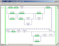
[attachment]

note that this represents a do-nothing “gobbly-gook” rung that I threw together at random just for this post ... do NOT try to understand it ... but the point remains, we COULD understand it if we had to ... hint: skip over all of the “BST” and “NXB” and “BND” instructions ... they stand for “branch start” and “next branch” and “branch end” ... but they do NOT affect the actual True/False outcome of the rung ... now let’s start reading the rest of the instructions on the rung IN THEIR ORIGINAL ORDER ...

XIC I:2.0/0

means “go look in bit/box I:2.0/0 and see if there is a 1 stored there” ... if there is a 1 stored there, then this instruction will be “true” ... if there is NOT a 1 stored there, then this instruction will be “false” ...

XIC I:2.0/2

means “go look in bit/box I:2.0/2 and see if there is a 1 stored there” ... if there is a 1 stored there, then this instruction will be “true” ... if there is NOT a 1 stored there, then this instruction will be “false” ...

XIO I:2.0/6

means “go look in bit/box I:2.0/6 and see if there is a 0 stored there” ... if there is a 0 stored there, then this instruction will be “true” ... if there is NOT a 0 stored there, then this instruction will be “false” ...

and so on and so on ... we’ll skip ahead here in our example ... BUT ... remember, the processor can NOT skip ahead ... he has to keep plugging right along ... step by step ... instruction by instruction ...

OTE B3:0/12

means “if the logic up to this point is true, then go write a 1 into bit/box B3:0/12 ... but if the logic up to this point is false, then go write a 0 into bit/box B3:0/12”

and another quick skip ahead here in our example ... BUT once again ... remember, the processor can NOT skip ahead ... he has to keep plugging right along ... step by step ... instruction by instruction ...

OTE O:3.0/2

means “if the logic up to this point is true, then go write a 1 into bit/box O:3.0/2 ... but if the logic up to this point is false, then go write a 0 into bit/box O:3.0/2”

the basic idea of the approach I’ve just outlined is that it allows you to ANALYZE ANY RUNG (I repeat: ANY rung) – STEP BY STEP – in exactly the same order that the processor scans it ... specifically, if someone tells you that the processor’s scan is “too fast” or “too unpredictable” to be analyzed and understood, that’s simply hogwash ... the approach that I’ve given you here goes MUCH deeper than simply looking at the green highlights on the screen display and trying to figure out whether or not we have a "true path" through the rung logic at any one time ... (just in case you aren’t already aware of it, the green highlights on the screen can LIE to you) ...

if this is the type of stuff that is puzzling you, don’t feel alone ... many of my students suffer from the same problems ... and some of these guys are maintenance technicians who have been struggling with PLC systems for years ... "struggling" because they’ve always based their troubleshooting techniques on ideas that are not always 100% correct ...

anyway ... read through this a few times ... and maybe take a quick look at this:

previous post on processor scan

if you need more help, post again ... and try to attach a specific example of what’s bugging you ... try to break it down as far as you can in your post ... then identify the specific areas that are giving you the most problems ... we’ll try to help you over the hard spots ...

finally ... you are certainly not the only one confused by this stuff ... I've been there - and done that ...

gobblygook.jpg
 
Last edited:
Ron has a good post here, but I'm going to add a bit of my own expierance.

When I 1st started in the busniess, all the controlls I ran into were real live relay logic. Most with hunreds of relays, and 4 or 6 times the contacts, a few dash-pot timers, and some rotary counters etc..

At first troubleshooting was very diffucult for me, and I finally asked an old timer engineer from Texas how he keeps track of all this stuff in his head. Turns out they used a abacaus like device to keep track of which coil would be on, or off, as they manually steped through proffing the drawing. So I made a device in the shop that had about fify slides and a window for each. It was about the size of a legal pad with two colums. On the right of the slide window was a listing of coils, on the left for each coil was a slide window (red for on, black for off). The lables were on a paper strip that could be removed and replaced for another controller. I always kept the label strips on the job doc package for future use. Eventually after a while I learnd to keep trak of things without the abacaus. Now days I tend to do my programming online, and now the PLC software does it for me.

And that's the story of my humble beginings....

Mike.
 
Hester,

There is no replacement for hands on learning. If you can get a spare PLC and start "playing" with it you will be miles ahead of just reading about RLL. Expecially helpful are the Online Display modes in modern PLC's.

Despite Ron's warning about the green "true" indicators when online with a PLC I still find them invaluable. For simple rungs they won't lie to you. For starters program this simple rung:

---] [-----( )-

where the contact is a Selector switch you can actuate. Download, run and play with the switch while watching the online display.

Then try these:


SS1 SS2
---] [-----] [-----( )


SS1
+---] [--+---( )
| |
| SS2 |
+---] [--+


With each rung, play with the switches to see what they do. These rungs are basic "and" and "or" circuits. Playing with them will explain why they are named as such. Most other rungs can be broken down into simpler "and" and "or" sections. Understanding these two constructs should definately be your starting place.

The next best inexpensive substitute for a real PLC in online mode would be the RSLogix-like simulator from The Learning Pit. You can perform the same experiments with this software but dont' need a real PLC.

nOrM
 
I think you guys are misunderstanding Hester. What I belive he is talking about is trying to follow a process through hundreds or maybe thousand of lines of code where one pushbutton could affect the state of many,many rungs. I think Hester knows how to read the code, write some code, and can follow relatively simple code, but when it comes to huge processes and tons of logic, nada.

I sometimes have to sit for a few hours and look at the logic and go over it in my head time and time again before I understand it. Sometimes it is code I wrote myself but have not had to deal with it for years, because as time goes on I think your skill develop and you get better at it. I have looked at things I did a couple years ago and thought, "What the hell was I thinking"?
 
first of all, thanks to Norm for pointing out that my earlier post might easily be misread ...

Despite Ron's warning about the green "true" indicators when online with a PLC I still find them invaluable. For simple rungs they won't lie to you.

I certainly didn't mean to imply that the green highlights were useless ... naturally they're the first things that you should look at when you're trying to analyze a rung ... BUT ... they should not be ALL that you look at ... even for simple rungs like these:

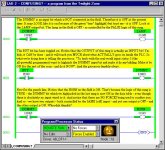
[attachment]

note that this is NOT a recommended way to write a production program ... but it does go a long way toward showing what can happen if the green highlights are the ONLY thing that you look at when trouble pops up ... specifically, it would be extremely difficult (if not impossible) for most beginners to troubleshoot what we see in the figure above IF they did not know anything more than the old "green means true" rule of thumb ...

Hester admitted to being somewhat confused when it comes down to reading ladder logic rungs ... I've found that most of the confusion in this area is caused by the following three issues ...

(1) how do the real-world inputs and outputs get into and out of the PLC? ...

(2) how does the processor execute each one of the instructions in the program? ...

(3) in what order does the processor execute the instructions in the program? ...

once a person has a complete understanding of each one of these issues, most of the confusion eventually just seems to melt away ... of course it always takes a certain amount of practice to get “quicker” at analyzing programs but once these basic issues are nailed down, then it’s just a matter of time and effort before everything starts falling into place ...

hijack.jpg
 
If you didnt learn actual relay logic prior to programming then I can understand why it could be confusing. I struggle with all of it but RLL I can understand because I have worked with relays for years.

I have a simple approach to understanding RLL, relays etc. Its based on electricity...bear with me. You know that an outlet has electricity in it so if you plug in a lamp then it will come on when the switch is flipped. It all comes down to this:
Code:
VOLTAGE                                           Voltage common
   |                                                    |
   |                                                    |
   |------------[switch]----------------------{lite}----|
Switch closed then light is on, switch open then lite is off.

A plc doesnt change the laws involved with electricity, what it does is allow you to manipulate the data associated with I/O.

If the above switch was a Normally closed device, a prox?, then the light would be on as long as the prox DID NOT detect.

In a plc though you can manipulate that N.C. prox to turn on a bit or output when its open or closed.
Code:
        prox               Output
|-------[ ]-------------------(ON}---|
Since the prox is closed (N.C.)the XIC will see it closed and turn on output.
        prox               Output
|-------[/]-------------------{OFF}--|
XIO will see the prox closed so will keep output off.
This confused me for a long time because i couldnt understand how if the switch was closed and "a path of electricity" was created the rung would not be true.

All it amounts to is "manipulation" of data. The instructions in the rung must be "true" for the rung...ie output to be true. A PLC allows the inputs and data to be manipulated to provide what is needed to make the rung true at the appropriate point/time. Technically this is true with any form of plc programming, ladder logic is just a style of graphical programming based on old relay logic.

The point I am trying to make is DO NOT OVERTHINK the issue. If looking at relay ladder logic then all you have to do is determine if the instruction(s) are true for the output to be true. Another thing is never expect to understand some things, like PID or other high end instructions when you first see them. There will always be something that requires some studying.

Jeez I ended up rambling.
 
and it looks like Jnelson and rsdoran have posted a couple of very good points ...

from Jnelson:
I think you guys are misunderstanding Hester. What I belive he is talking about is trying to follow a process through hundreds or maybe thousand of lines of code where one pushbutton could affect the state of many,many rungs.

yes, I for one could easily be misunderstanding him ... and if so, I certainly hope that he’ll post again and give me another chance to help ...

now as for following a process through “many, many rungs” of logic ... I’ll admit that such an exercise CAN certainly be time-consuming and maybe a little bit frustrating ... BUT ... I’ll stick by my position that an exercise like this is still perfectly doable as long as it’s approached in a step-by-step systematic manner ...

the major thing that bothers me is the way that many people consider the processor’s scan to be “too fast” or “too unpredictable” or “too random” to be understood ... actually there ARE ways to analyze the processor’s scan and fully understand EXACTLY what’s going on ... instruction-by-instruction ... and rung-by-rung ...

I liked Mike’s “abacus” approach to recording the program logic ... personally, I usually just draw a separate little box on paper to represent each bit that I’m working with ... then I record the “1” or “0” status of each bit with a pencil as I move through the program ... of course I only need to use this approach when I’m working on something a little more complicated than the average run-of-the-mill program ... but it’s nice to know that there IS a systematic approach which will always give me the answer to even a knotty problem ... just as long as I take my time and “scan” carefully through the program using exactly the same rules that the processor uses when he makes his scan ...

basically what I’m saying here is that once you learn to “think like the machine” then it’s a lot easier to understand the reasons why something doesn’t seem to work the way your human mind thinks it should ...
 
Last edited:
¢ ¢

Like Ron Doran, I look at the rung like a circuit. I'm just trying to make a connection from one side to the other.

One thing I try not to do is to get too bogged down in the details. I have to remind myself constantly to "look at the big picture".

The contradictory part is that you can't let the picture get too big. Here's what I mean:

In troubleshooting, the basic question is "Why doesn't the #%&$# machine work!!!.

That's too big of a picture. Take a step closer and ask: "What should be happening right now?" - The answer may be: "The motor should be coming on". Then, first thing I do is find out if the PLC is indeed trying to turn on the motor.

I look at Ron (Beaufort)'s gobbly-gook code above, and sure enough, O:3/2 isn't energized. So the question become: "Why?"

Thankfully, the thing that's holding up the process isn't that tangle of imputs. There's a clear path through I:2/8 - I:2/10 - I:1/7.

But there are still three thing that are holding up the works: B3/7, O:4/4 and I:9/14.

Now since Ron was kind enough to leave off the annotation, I'd hazzard a guess that O:4/4 and I:9/14 are related - that once the output is made, the input will come on. So I'd first write down B3/7 on a scrap of paper (if, in my travels, I see that it's hanging up the works, I'll change course and go after it instead". Then I'd do search or cross-reference to find out why O:4/4 isn't on, and off I'd go.

But I may already be too deep into the weeds already. Perhaps it's time for a big picture view. I've asked "Why isn't the motor coming on?" Well, why do I think that the motor should be coming on? What step in the sequence am I on? What's really going on here? Where does the PLC think that it is? It could be that the PLC, for some reason, thinks that the motor started, did it's thing, and is now on to something else. Trying to find out why the motor isn't coming on is a fool's errand. The PLC isn't stuck trying to start the motor. The PLC started and stopped it in one scan, did some other cleanup, and now is waiting for a physical condition to happen that can't, because it didn't alter the real world enough to make it happen.

(Example: The motor is supposed to pump water into the tank until a level switch is made. Then it's supposed to run the agitator (which is interlocked with the level switch), and proceed to time when it's confirmed that the agitator is running.

Except that someone bumped into the tank, causing the over-sensitve level switch to make for just a moment. So the pump stopped (at "level"), but the agitator doesn't come on, beause there's no liquid in the tank.

If you're not taking the "big picture" view, you miss the fact that you and the PLC are not trying to accomplish the same goals.


So what winds up happening is that, when I'm troubleshooting, I don't clutter my mind with facts. There will be lot's of code that I just ignore, because I know it's not applicable to my current problem. (Sometimes that's wrong, but it's one way to get going. When it IS wrong, I'll use the formal troubleshooting techniques that Ron (B) describes).)

I've seen enough code in my life that I can often tell, just by the general shape of it, whether there's a problem with it or not (Ron's gobbly-gook code set my teeth on edge. I'd spend quite a bit of time looking at that one before I was convinced that there wasn't at least a cleaner way.


Ron Beaufort said:
of course I only need to use this approach when I’m working on something a little more complicated than the average run-of-the-mill program

I don't know, Ron. A program that runs a whole mill is usually pretty complicated. :p
 
I've seen enough code in my life that I can often tell, just by the general shape of it, whether there's a problem with it or not (Ron's gobbly-gook code set my teeth on edge. I'd spend quite a bit of time looking at that one before I was convinced that there wasn't at least a cleaner way.

Sometimes I think I have spent a lifetime looking at things like that, there is no doubt I have spent many overtime/middle of the night hours looking at this kind of code with no annotations. I have gotten to an age (or point in life) where sometimes I open a cabinet or connect to a PLC (to troubleshoot) and want to start from scratch....it would have to be easier.

What it boils down to Hester.....you aint alone.
 
Thanks for all the replies.

I'm currently absorbing the posts. Thanks so much for the replies.

I've come to the conclusion, that there is just no way for me to conceptualize a machine, that is to create a 3D mental image of the equipment, without first walking around a getting to know every input.
I'm a "Got to understand the whole machine before I troubleshoot" type of guy.

It always takes me longer, but my repairs are generally more accurate than a "shotgunning" tech (by shotgunning I mean replace parts until Betsy works again).

I can deal fine with internally generated bianary outputs if I understand what the inputs are, and have physically seen them for myself. I'm just not one of those guys who can look at RLL and go "The Problem IS HERE!"

Typical scenario I deal with: "such and such is broken - go fix it, customers are waiting, we need it yesterday, etc...
So I walk up to a piece of gear I don't even know where the On switch is, and go to work.

I just get frustrated, because I wish my IQ was about 100 pts higher, and I could breeze right to the problem. But that ain't me. I have to stare, take a measurement, scrath my chin, ponder it.

I was hoping you guys had some kind of magic way to grasp a machine in your mind and quickly diagnosis it. I've work with guys that are magic - they can do that. I'm not an idiot, but I can't reach into the guts of a machine, pull out a battery backed up Eprom, short the reset line, and viola the machine resurrects back to life, simply because it seemed like the right thing to do... Magic. Some guys can.

I've never bothered to try to model their thought processes so I could do it too, until now.

Hoping to model your magic....
 
Hester-

By and large there is no sure-fire, easy way to quickly conceptualize an automation process. Now, some would debate whether you really need to fully understand the process to troubleshoot it. I tend to believe you do.

However, there are two different varieties of 'experience'. One is simply knowing what to do because you've seen it before. "Every time this light has come on in the past, pressing this button has fixed the problem". This is the same kind of 'experience' milk cows exhibit when they go to the right stall in a barn at milking time. Don't get me wrong; this is valuable experience. It allows one to very quickly do what is needed to achieve an end. But on the flip side of that, don't think yourself any less capable when others who use this type of experience to solve a problem. You just haven't seen enough yet to develop this experience. This is essencially the basis for expert systems.

The other variety of experience is what you are looking for. This is made up of methods and processes that allow you to determine a cause based on one or more previously unrecorded or unrelated effects. Basically, this is thinking your way through a problem. While there are some generally accepted methods on this it is a largely personal thing. You need to develop your own style. Go with what works for you.

When I troubleshoot, for example, I try to keep my scope as limited as possible and expand it as necessary as I go along. That just works for me. It looks like you like to get a greater conceptual overview before you start. If that works for you go with it. As long as you come to the correct solution that's OK too. I would tend to suggest, though, that if time is a factor you limit your overview as much as possible, at least at first.

Good luck and keep learning.
Keith
 

Similar Topics

Dear team, We are constantly facing M07 incremental loss on one of our kinetix 6500 safe torque. We have changed Servo motor (MPL-B4530K-MJ72AA)...
Replies
1
Views
110
I have an application using an incremental encoder and then I convert it to degree (0-360) using calculation program. For a while, the calculation...
Replies
7
Views
239
Hi all, I am using a B&R X20 unit and want to integrate an incremental encoder (OUT A, B, & Z). I have three BOOL digital input pins for my A,B...
Replies
3
Views
446
I have a question regarding the features of the so called incremental (velocity) form of the PID controller. As far as I understand this form in...
Replies
14
Views
2,517
I posted how computers work at the fundamental level on Reddit if you want to check it out. Pretty fun stuff and thought I would share it here as...
Replies
8
Views
3,167
Back
Top Bottom