Help with loop controller for electro-pneumatic valve control

emeka.ike

Member
Join Date
Sep 2014
Location
Ran
Posts
3
Hello guys,

I'm in a bit of a dilemma - not very clear on the operation the typical PID controller. Here's the issue:

A client has a turbine whose outlet (exhaust gases) is used to power a chiller. The exhaust gases are channelled through a control valve (with a positioner) which he would like to open/close to different percentages depending on the conditions in the process.

He simply wants to observe the process physically (There is no sensor installed on the process to read/monitor PV parameter), then depending on the process conditions, he can decide to open the control valve to maybe 20% as an example, and leave the valve in that state until he has need to open/close it to a different percentage value. Basically all that needs to be done is to send the appropriate milliamp (4-20mA) signal to the valve positioner (more like using a 4-20mA signal injector to send open/close signals to the valve positioner). He does not intend to run the system in Auto.

As a solution, I'm considering using a single loop controller (UDC-1700) but not very sure if it would fit the purpose. The idea is to run the loop controller in Manual Mode, and allow the user set the Output percentage to the value he desires.

I just need to know if this will work, and would appreciate if you please provide some clarification on these (I seem to have it all jumbled in my head).
  1. Will the fact that there is no PV input to the system - (I do not intend to have the system run in Auto) have any negative impact on achieving the above control philosophy?
  2. When one says "When in Manual mode you have access to change only the Output", what does that mean? Does it mean that the system ignores the PV and simply converts whatever Setpoint value is entered on the controller directly to a corresponding 4-20mA output to drive the valve (0-100%)?

Thanks for your time!
 
Will the fact that there is no PV input to the system - (I do not intend to have the system run in Auto) have any negative impact on achieving the above control philosophy?

Probably not. A controller in manual mode is technically a manual station. The output will hold whatever percentage it is told to hold forever.

One possible issue is if no PV is present, the controller will detect the absence of an input and do something, like declare an error in the display, flash INP 1 FAIL, or something like that. A workaround would be to configure a controller for T/C input and short the input terminals so the display shows ambient temperature. A PV of ambient temperature is meaningless to a manual station, though. Any PV is meaningless to a manual station.

When one says "When in Manual mode you have access to change only the Output", what does that mean? Does it mean that the system ignores the PV and simply converts whatever Setpoint value is entered on the controller directly to a corresponding 4-20mA output to drive the valve (0-100%)?

A manual station controller (a controller in manual mode) pays no attention to either the setpoint (SP) or the process variable (PV).

It only pays attention to the value/position of the output adjustment. On a UDC 2500, the up and down arrow keys adjust the output up or down when the controller is in manual mode.

A client has a turbine whose outlet (exhaust gases) is used to power a chiller. The exhaust gases are channelled through a control valve (with a positioner) which he would like to open/close to different percentages depending on the conditions in the process.

There's a reason there's a control valve installed where it is. The manufacturer would not incur the expense to put a control valve there, particularly if alloy materials are needed to hold up to the temperature exposure.

So the issue becomes, what performance factor is being affected by playing around with manually controlling the valve position? I don't know, I'm not a turbine guy, but the valve is there for some reason that should be accounted for.

As a solution, I'm considering using a single loop controller (UDC-1700) but not very sure if it would fit the purpose.

I know the UDC2500 runs in manual mode. I'm not sure about the 1700, you need to check the manual.
 
screen shot from UDC 1700 Quick Start guide:

Manual_mode_operation.jpg
 
Probably not. A controller in manual mode is technically a manual station. The output will hold whatever percentage it is told to hold forever.

One possible issue is if no PV is present, the controller will detect the absence of an input and do something, like declare an error in the display, flash INP 1 FAIL, or something like that.

You are right Danw, the unit does have a "Sensor Break Protection" as pointed out in the manual, however, I'm not sure if this is only applicable when in Auto mode.


A workaround would be to configure a controller for T/C input and short the input terminals so the display shows ambient temperature. A PV of ambient temperature is meaningless to a manual station, though. Any PV is meaningless to a manual station.
By T/C input, you mean configure input as Thermocouple Input and then short them?


A manual station controller (a controller in manual mode) pays no attention to either the setpoint (SP) or the process variable (PV).

It only pays attention to the value/position of the output adjustment. On a UDC 2500, the up and down arrow keys adjust the output up or down when the controller is in manual mode.


There's a reason there's a control valve installed where it is. The manufacturer would not incur the expense to put a control valve there, particularly if alloy materials are needed to hold up to the temperature exposure.

So the issue becomes, what performance factor is being affected by playing around with manually controlling the valve position? I don't know, I'm not a turbine guy, but the valve is there for some reason that should be accounted for.

Well, the client insists on not running full Auto at the moment (so there will be no sensor for PV input). But should he wake up tomorrow and decide that he wants the system to run in Auto, I believe all that needs to be done will be to modify the process to include a PV sensor, set the controller to Auto mode and wire up the PV sensor to its input.

I know the UDC2500 runs in manual mode. I'm not sure about the 1700, you need to check the manual.

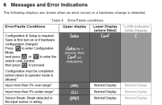
Sensor break detection.PNG Error Messages.PNG
 
screen shot from UDC 1700 Quick Start guide:

Manual_mode_operation.jpg
What can I say Danw? Thanks for taking the time to search through the manual and pulling this out. It is well appreciated.

This is theoretically what I intend to achieve. Manually set Output power to appropriate level, causing valve to open to desired percentage and stay in that state until user decides to change it again. Like you pointed out, I believe it should work in Manual mode even without the PV.

As a question, what sort of solution would you have proffered assuming you had to achieve the same control philosophy as this? Would you have trod the same route as I am?
 
As a question, what sort of solution would you have proffered assuming you had to achieve the same control philosophy as this? Would you have trod the same route as I am?
Yes, except I'd use a UDC2500 because I can read the characters like a regular alphabet and the configuration matrix has been the same since 1988.
 
simplest answer is to have a potmeter:
depending on the supply voltage you have and the needed voltage on the valve, some are 5 Volts some are 10 standard is 24 Volts.
suppose you have 25 Volts and the valve is 5 Volts at 20 mA (just as example)
the max would be 20 mA so the steady resistor would be 1 kiloohm
the min is 4 mA 5 kiloohm. a potmeter of 5 kiloohm is working just fine.
no need for electronics.block it mechaniccaly on 1 kiloohm(20%) to prevent high current.

You can also make a calibrator with a LM317 (search this forum for it.)

another way is to use a broken controller from anywhere and use the manual setting.
 

Similar Topics

Hello all! I come asking if anyone has had this situation. I have a Micro820 controller that sits idle for some long periods (I use it to count...
Replies
5
Views
1,323
I need a little help with a project I have been thinking about. We have a belt line that is fed by a gravity door (pretty much a hydraulic...
Replies
14
Views
2,733
Hi all, I have a request from client as follows, There's one PID for Control valve which would be controlling on basis of temperature. One...
Replies
1
Views
1,517
Hi, I am doing a course in I&C Engineering. I have the following question which I am stuck on...
Replies
1
Views
1,410
I have an application coming up that requires a metering pump to be controlled via a PowerFlex 525 VFD. Commands to the VFD are to be sent via...
Replies
5
Views
11,230
Back
Top Bottom