PLC5 'Slot Addressing'

rlmts

Member
Join Date
Jul 2003
Location
Newport, S.Wales, UK
Posts
120
Hi,
I need to add two I/O cards to a PLC5 installation.
(one 16 bit input and one 16 bit output card)

The processor is a 5/40L
In RSLogix 'Processor Status' it shows bits 11 and 12 in word S:2 set for '2 Slot addressing'

Does this setting fix the method for all Racks? Hence no need for me to remove racks to check the dip switches?

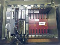
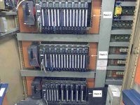
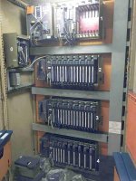
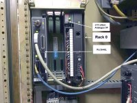
Current set up (Also see attached pics)
There are 4 racks...
Rack 0 (4 Slot?) with...
PLC5 Processor and Analogue input card + 2 spare slots

Rack 1 (12 Slot) with...
Servo Controller and Servo Expander modules, plus RS232 I/F + 7 spare slots

Rack 2 (16 Slot) with...
Various 16 bit Digital I/O but O:027 not used
(if I remember rightly 027 address used internally? PLC2 hangover?)

Rack 3 (16 Slot) with...
Various 16 bit Digital I/O

Rack 4 (16 Slot) with...
Various 16 bit Digital I/O with some spare slots for output cards ONLY (2 Slot Addressing)

I was hoping to add one 16 bit input and one 16 bit output card to rack 1 but not sure about mixing the 16 bit cards with the Servo cards which are block transferred (8 bit?) I read something about this 'mixing' problem somewhere. (Suspicious about the remainder of this rack not being used by manufacturer!)

Although, installation was originally PLC2 (see old processor still in panel) not sure if this is relevant?

To summarise, my questions are...
Based on processor status file word S:2 will all racks dip switches be set for 2 slot addressing?
Can I install one 16 bit input and one 16 bit output card into rack 1?

Thanks in advance
See attachments of the installation
PLC5_Rack_0.jpg PLC5_Rack_1.jpg PLC5_Rack_2-3-4.jpg PLC5_Rack_0-1-2-3-4.jpg
 
Last edited:
The adressing method is set by dip-switches in the physical chassis. The S:2/12 - S:2/15 bits are read from the chassis in which the CPU resides.
The switches only pertain to the particular chassis. In another chassis the settings may be different.

So for chassis 0, 2-slot addressing is selected, and you can insert a 16-channel input card and a 16-channel output card in the 2 free slots, and in the I/O image, the corresponding input and output words will be linked to the 2 cards.

edit: Damn, I missed that you meant rack 1, and not rack 0.
You have to investigate what kind of addressing is setup for chassis 1.

N.B. You wrote "Can I install one 16 bit input and one 16 bit input card into rack 1?", which I think is a typo. You probably meant "Can I install one 16 bit input and one 16 bit output card into rack 1?"

N.B. In AB lingo "rack" means 8 words in the input image table, and 8 words in the output image table.
"chassis" is the physical rack.
 
Last edited:
Thanks Jesper, yes that was a typo (now corrected)
So I have to dismantle the chassis with the Servo cards in to establish the addressing method, correct?

When I know the addressing method I guess I can still add I/O to this, regardless of there being 'block transfer cards' in this chassis. Will it just dictate the type of cards that can be installed?

By virtue of the fact these Servo cards are in this chassis, does that tell us what addressing method they would have needed to use?
(Half, one or two slot?)
 
So I have to dismantle the chassis with the Servo cards in to establish the addressing method, correct?

not necessarily ... in many (most?) cases you can do some "deductive reasoning" to figure out what addressing mode is being used in any particular chassis ...

for example:

suppose that you can identify a "special" pattern of LEDs on a certain module located in your "chassis of interest" ... for example: suppose that LEDs 01, 02, and 03 for a particular input module are staying ON (and no other input module has that same pattern) ...

now find that same pattern of ONEs in your input table ... from that you should be able to deduce whether the chassis in question is using one-slot, two-slot, or half-slot addressing ...

TIP: avoid using the FIRST couple of modules for this operation ... I can explain if you like - but my typing time is very short today ...

BIGGER TIP: many (but not all) PLC-5 projects have their "I/O Configuration" set up to show the "Rack Addressing" being used for each chassis ... while this MIGHT be a "starting point" for you – do NOT blindly accept the information shown here ... this feature is strictly "documentation" which has been entered here by some human being ... the processor doesn't make use of this information – so it can definitely be wrong - even if the system is working perfectly ...

good luck with your project ...
 
Last edited:
There is also the risk that the original programmer has decided to configure a smaller rack than is physically available, for example because he dont count on ever using the unused slots in rack 1.
It is possible to assign 1/4, 1/2, 3/4 and 1 rack at a time.
For example if 1-slot addressing is used, and only a 1/2 rack is assigned to chassis 1, then only the first 4 slots are available in that chassis.
Probably not the case, but you should investigate it.

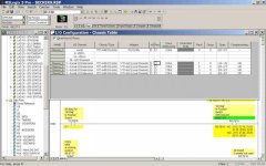
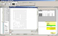
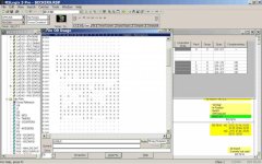
In RSLogix 5 look in the IO Configuration - chassis table.
 
Thanks Jesper,
The problem with the 'deduced' method is that there is no digital I/O in the second chassis (Rack 1) Just the Servo Controller and Expander cards.

I have attached a snapshot of the I/O configuration file, but as you say, cannot be relied upon. This machine was originally PLC2 so I am guessing whoever upgraded it went to a little effort in recording the I/O so is possibly correct (shows rack 1 set as 2 slot addressing)(but shows Rack 0 as 16 slot!)

Q1) When the addressing method is identified I guess I can still add I/O to this chassis, (regardless of there being 'block transfer cards' in this chassis)
Will the addressing mode found simply dictate the type of cards that can be installed?

Q2) By virtue of the fact these particular Servo cards (1771-HS & 1771-ES) are in this chassis, does that tell us what addressing method they would have had to set when installing them?
(Half, one or two slot?)

By the way, in this particular arrangement of Racks/Chassis...
The PLC and Analogue in are in what I called Rack 0 (1st chassis)
The Servo cards (and no digital I/O) are in what I called Rack 1 (2nd chassis)
All I & O 020 addresses are in what I called Rack 2 (3rd chassis)
All I & O 030 addresses are in what I called Rack 3 (4th chassis)
All I & O 040 addresses are in what I called Rack 4 (5th chassis)

Q3) How do I find out what rack configuration is used (1/4, 1/2, 3/4, full)
Is this set in the local chassis adapter card?

untitled6.jpg untitled3.jpg untitled4.jpg
 
Q1: If there are no "un-assigned" slots according to the addressing type, and no size of rack, then yes.
The "span" for chassis 1 is 1/0-1/5, meaning 6 words, which will cover the entire 12-slot chassis if 2-slot addressing is used. So my guess is "yes".
Block Transfers use the 1st word assigned to the slot in question. Block transfers do not affect neighbouring slots.

Q2. No. These probably use block transfers for all their comms with the CPU.
And this is probably why the expansion chassis are connected to the CPU via an "local bus" adapter and not RIO, since the local bus expansion is much faster than RIO for block transfers.
So you cannot deduce the addressing method from the location of these modules.

Q3. If you can, power down and remove the adapter modules to investigate the switches. If you cannot do that, you can investigate the block transfers for the servo cards in the PLC program. The rack/group/slot information there should be compared to what you believe is the addresses used for these modules.
Apart from that, when you eventually get to install the new cards, you have to power down anyway, so you have the opportunity to confirm if what you have deduced is correct.
 
Thanks Jesper,

I'll check if I can get the plant down to examine the adapter/chassis settings for rack 1 (2nd chassis)

If I was to slot a card into this chassis, what is the worst that can happen? (Assuming the plant is stopped/idle and in manual mode)

Processor goes to STOP perhaps?
 
Thanks Jesper,

I'll check if I can get the plant down to examine the adapter/chassis settings for rack 1 (2nd chassis)

If I was to slot a card into this chassis, what is the worst that can happen? (Assuming the plant is stopped/idle and in manual mode)

Processor goes to STOP perhaps?

PLC5 systems are NOT hot swappable, don't do it.
 
Thanks Mickey,

Really explained myself badly there!
I wouldn't have done it with power on.
(Jesper also mentioned this earlier)

What I should have said was ... "what's the worst that can happen when I power it back up"
Not sure why I mentioned machine in manual mode etc. How stupid of me!!

I think I was trying to assure you guys that there would be no machine sequence issues whilst in manual/Estop etc.
 
Nothing bad can happen if you insert a new module in one of the empty slots (after powering down of course).
Worst thing that can happen is that you cannot get the I/O in the new module to respond.

edit: Except for if the new module overloads the power supply, which is unlikely. But have to mention it.
 
Ok, thanks Jesper.
I may just find some spare cards, plug them in, switch on and check if I can address/control them in the ladder/data tables.
Initially assume 2 slot addressing and fit a 16 bit input followed adjacently with a 16 bit output in last two slot positions.
 
Nothing bad can happen if you insert a new module in one of the empty slots (after powering down of course).
Worst thing that can happen is that you cannot get the I/O in the new module to respond.

edit: Except for if the new module overloads the power supply, which is unlikely. But have to mention it.

It all depends on your definition of 'BAD'.

IF the new module is an OUTPUT module, once the PLC goes back into RUN, the output image table for that rack/slot/group will be transferred to that module, and any active (i.e. '1') bits in that image will be reflected on the module, and, by extension, any field wiring. It does not matter that there was never a module in this slot. It does not matter that there was never any programming for this slot. The ONLY thing that matters is the contents of the output image table.
---
Now, if the module is an INPUT module, once the PLC goes back into RUN, the module will transfer data into the INPUT image table, over-writing any data which was there. IF the existing program uses this image area for any reason, the reaction of the program will be based on the voltage status on the field wiring arm, and NOT on the input image data.
 

Similar Topics

Hi All, I am looking at a future project that includes a PLC5 with some digital I/O. Its been a long time since I have worked on the PLC5...
Replies
4
Views
1,584
Hi all, I am currently working on a project to convert three PLC5's to CLX using the Rockwell migration tools. I was wondering if it were...
Replies
16
Views
9,827
Hi Friends, I'm to swap a few Digital Outputs (XV) from their slot to a different slot. The Processor is a PLC5/30 (Ethernet). I'm more familiar...
Replies
8
Views
2,194
I am using the following formula and I am getting error, Invalid Expression - too many closing parenthesis. when i copy the formula to notepad or...
Replies
4
Views
145
Back
Top Bottom