Power supply redundancy module

lncabin

Member
Join Date
Nov 2014
Location
LA
Posts
8
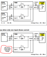
I've attached the circuit diagram for a redundancy module. I'm a mech so bare with me. I'm trying to understand how this circuit is working to get an understanding of how my power distribution circuit is operating.

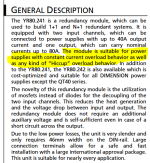
From what I read on the tech specs is that 2x40A inputs from the power supplies will output 1x80A from the redundancy module. But if one power supply would fail then the output from the redundancy module will drop to 40A and thus I am really only providing 40A of redundancy?

http://www.pulspower.com/index.php?reqNav=product&objectId=161
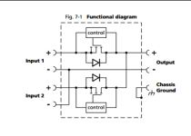
Capture.PNG
 
I do believe it not for failure redundancy, but more about unstable supply or a 40A Power Supply do the job most of the time and there's a bigger demand time to time.

Capture_PS_general.PNG
 
Last edited:
We use those for redundancy, if one power supply fails, the other picks up the load, essentially acting like parallel check valves. Of course, your max load shouldn't exceed what only one can supply.
 

Similar Topics

I have the power supply in the link below. If we want a breaker to isolate and protect the input side how would I size that correctly being 120...
Replies
8
Views
202
I am looking for power supply that I can mount on vertical DIN rail, and when mount that way is =< 4" wide. this is what I have now.... this is...
Replies
21
Views
578
I have Rhino 120 to 24 dc power supply and it has 2 Positive and 2 negative terminals on the DC side but no ground terminal. Should I connect one...
Replies
9
Views
434
We've still got a ton a PLC 5's installed and running. We lost a 1771-P7 Series B power supply. There are a lot of 1771-P7 series D power...
Replies
3
Views
236
Long ago, it was often a customer spec to always use a transformer for isolation of the control circuit from the rest of the equipment. For 24vdc...
Replies
5
Views
672
Back
Top Bottom