Beginner Timing Problem

RReasons

Member
Join Date
Mar 2016
Location
Tennessee
Posts
5
Hello everyone, I am a very basic beginner of PLC; I am currently in a class where we are going over PLCs. We have to complete Programmable Logic Controllers: Hardware and Programming - 3rd edition by Rabiee and the Manual first before we start on a actual PLC trainer by Amatrol for A/B 500 and 5000. In the book we are using LogixPro Simulator.
Like I said; this is for sure basic after reviewing questions through the forum, but I have read through the pls.net tutorials, my books timer chapter, other websites, looked at example submitted diagrams on this website, and so forth but I just am not understanding how to set this PLC ladder logic diagram up. I have around 20 questions for this Chapter and I don't want the answers for every answer by any means, but if possible could someone help me out with the first problem so I can actually understand how the timers and so forth would be set up? If so I truly appreciate the help!

Problem:
Using non-retentive timers to control the output ports.
1. When switch two (SW2) is closed, the red pilot light (RED_PLT) turns on, motor one (M!) starts running, and the bell sounds.
2. After ten seconds, M1 stops running and the white pilot light starts(WHITE_PLT)
3. Fifteen seconds after the process in step two has been carried out, RED_PLT, and WHITE_PLT turn off, and the green pilot light (GREEN_PLT) turns on.
4. Finally five seconds after the processes in steo three have been carried out, both motor 1 (M1) and motor 2 (M2) will start running.
5. If switch one (SW1) is opened, the process is halted.

I have tried everything I know but I just can't get the result I am looking for :-/

Again if any help could be provided so I can understand how this works I would be very grateful. I understood timers in EMC, but timers within PLCs are completely different, at least to me. Also any tips would be greatly appreciated!
 
Last edited:
So what have you tried? Show us what you have tried and we can offer advice/suggestions.

MY first suggestion would be tackle them one step at a time. Output M1 for example. Tackle that all by itself without the lights. What logic do you have for M1?

OG
 
That actually seems to be my trouble is, I have been trying to tackle a group at a time; I am on a schools old computer that is XP so it doesn't seem to have SnippingTool :-/. But I have been trying to tackle each step basically as a group with parallel. Then for every time a output turns off or on again I group it on the step that it is listed in, and I tried to list the outputs going from top to bottom in order that they are listed in the steps. Sadly...my first one I had was the closest, as I was only two-three that would not perform correctly, now I have changed so much that I have everything all messed up so bad I was about to start over, which you suggest anyways so that's good.
But here is what I have thus far.

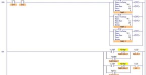
I have three timers listed as;
T1; Preset 100 TB=.1
T2; Preset 250 TB=.1
T3; Preset 300 TB=.1
(For some reason I thought I could perform with all TON, but Im confident now that i'm no where close)

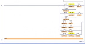
The outputs are listed here below; we are supposed to list them as so; O:2/0, but to save a little time i listed things simply as O:0 or O:1 in the "attempted diagram" below
RED_PLT = O:2/0
MOTOR 1= O:2/1
WHITE_PLT=O:2/2
GREEN_PLT=O:2/3
MOTOR 2= O:2/4
BELL: O:2/5


Like I said I have really got outside of my self getting aggervated by this skill, i feel like I have tried everything. Thank you again.
Rung Number & iNPUT Timer Inputs Output
-------------------- ------------ ------
2 SW1 SW2 ____ T:0/TT - T:1/DN(NC)___ O:0
| | |
| |_______T:0/TT ______|
|___T:0/TT___________| O:1
| |__T:1/TT_| |
| |
|___T:0/DN___________| O:5
|___T:1/DN___________| O:3
|___T:2/DN___________| O:4
|_T0/DN___T:1/DN(NC)_| O:2
 
Use Ctrl+Prnt Scrn to take a screenshot, paste it into Paint, then share it.
Your diagram is tough to make out (as ASCII art often is), but are you turning the Timer Timing bit high instead of turning the timer on? The TT bit is an indicator of timer activity.
Note that I've not used the LogixPro simulator, and could be mistaken for that platform.

Sorry for such a late reply; I do not have access to a computer outside of school, as soon as I get a chance to catch up from payments to school I am getting a computer because I am falling behind I feel like due to these PLCs -_-. But things can only get better.
Honestly sir, PLCs were going quite smoothly till this Chapter 8 I have started. So even though I have read Chapter 8 multiple times, and the tutorials here; frankly I'm not exactly sure what you are referring to when you say "Timer Timing". But I am about to go read over some statement definitions you referred to in my book and in the LogixPro software manual.

Also I did what you said; and I here is there PRNTSCREEN you asked for, I did not realize that is what that button was for. But I left it exactly like it was due to no access, but about to work on it some more after reading on what you spoke about. Thanks for the help again!
 
I have successfully figured out the problem! I actually ended up scraping my failed attempts , took a long sitting break reading your definitions you spoke of, and tried a different route like you suggested mixed with my type of layout and it worked on the first try! I truly appreciate the help but if you don't mind I will still take on the support, suggestions, tips, and so forth that you were going to throw my way regardless as I will take all the help I can get in this being so new in the subject! Thank you again
 

Similar Topics

Hi all, Writng a FB in ST on Beckhoff TC for a pulser which turns on and off on a cycle, is paused by turning bControlInput to FALSE, but resumes...
Replies
6
Views
248
So to start off: I have no experience with PLC's, but I'm good at figuring stuff out, but I need some help to know if my PLC is just dead in the...
Replies
2
Views
114
Dear all, First of all thanks for letting me join this forum. I just need some help in one of my programming exercises. Being a beginner...
Replies
6
Views
609
I am trying to connect to SLC5/03 using an FTDI usb to rs232 with female to female converter at 1 end... however I can not connect to it ... the...
Replies
8
Views
1,269
First time poster here so long story short i built my own trainer at work so i could toy around with various things and test things and learn...
Replies
25
Views
2,146
Back
Top Bottom