VFD as a transformer

dwoodlock

Lifetime Supporting Member
Join Date
Nov 2012
Location
Cincy/nKY
Posts
564
Hello All,

So beginning assembly on a new project, and it just occurred to me that I don't have a transformer for the servo drive that I just bought.

It uses 200AC(which sucks btw), so luckily I do have 480 3ph at the machine, but I need a step down transformer so that I can get my 200-220 instead of running a bunch of conduit and what not.

I don't have one on the shelf, so it will require ordering. I then realized that I do have a cheap SEW .75kw drive sitting on my desk that I've not used for anything yet, and Was wondering if anyone had ever tried using one basically as a transformer to supply another device?

I want to try this out for science, but I'm thinking it will be on a cheaper device.

feel free to call me an idiot or whatever you feel best demonstrates your point.
 
My only concern would be the fact that while you’ll be lowering the AC voltage you’ll also be reducing the frequency. How will the equipment that’s looking for 50hz or 60hz react to 25hz or 30hz?
 
I think that would require an abundant supply of "magic smoke" to put the servo drive back together after you power it up!!
 
If isolation is not an issue I would recommend getting two small single phase 480 to 120 step-down transformers and wire them in an auto-transformer configuration. If you need isolation I would recommend getting a 480 multi-tap primary to 120/208 3 phase secondary transformer rated for 1kw to have some reserve capacity for peak loading.

I don't know if using a VFD drive would be compatible due to the output waveform and peak voltages involved. It would probably require a line conditioner filter on the output of the drive. By this time you have spent the money you could have bought the correct transformer. If you do decide to risk it, then you could set the max freq. of the drive to 120 hz linear output but adjust the input control voltage so that the output freq. is only 60 hz. Then, check to see if the voltage is at or near your required 200VAC.
 
Last edited:
You now how a VFD works right?

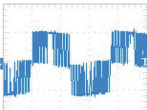
It takes the 3 phase voltage and runs it through a rectifier and turns it into DC voltage. Then you have some capacitors to take the wors ripples away. Then it shops up the DC voltage again at say 4kHz and makes a really bad looking AC from the DC with lots of spikes and harmonic overtones. It uses puls width modulation but it has the same voltage as the incoming voltage.

With a motor being a big inductor it will smooth out the voltage from the VFD to something looking like real AC.

That is not something you want to power your servo drive with (and the peak voltage will be the same).

pwm-voltage-at-vfd-output.jpg

http://www.variablefrequencydrive.org/vfd-harmonics-increase-motor-losses
 
Last edited:
Yeah I know that a vfd waveform is not exactly the same, but I figured I would try it anyway with something cheaper, just to see what happens.
 
Usually when you try to "make it work with something cheaper," you end up spending a LOT more money than you would have had you just used the correct components to begin with. Honestly, you're going to end up spending $2 in the long run to save 50 cents today.
 
Bad idea.

a servo motor transformer is designed with the servo power requirements in mind.

a vfd is designed with a motor power requirements in mind and they just don't
match.

the servo speeds up, slows down, stops as we all know and thus requires different levels of power.

the vfd looks for a load (stopped) when you power the servo up and you have
+/- so much power leeway. when the servo takes off, the vfd will most likely see it as a fault.

I may be wrong, I have been in the past, but I think you will smoke the vfd if you use it. if I am wrong, someone please correct me.

You are also violating electrical code rules by using the vfd in a manner in which it was not designed or ul approved.

regards,
james
 
The VFD PWM output DEPENDS on the connected load being an inductor, like a motor winding. The voltage output is not really AC, it is "pseudo-AC", meaning "almost-as-if". it's the inductive time constant of the motor that makes the PWM DC pulses look like AC power to the motor. Without the inductor, it's just a flurry of DC activity.

Inside of your servo amplifier, it likely has a transformer somewhere, but the first thing it will have is a diode bridge rectifier. That diode bridge will not conduct correctly based on the DC pulse strings getting to it. So to make it work at all, you will have to, at the very least, add a reactor as an inductor between the VFD and the servo amplifier. You might as well just buy a transformer and do it right the first time.
 

Similar Topics

Hello, It is mandatory to use VFD IF i use IE5 electrical motor? What happens If connect it directly as delta without VFD? Please look at motor...
Replies
1
Views
119
Hello, I am trying to setup on plc so If I enter 60 jph (job per hour) it will send the vfd hertz based on what jph is entered by...
Replies
2
Views
152
commentaire communiqué siemens s7-1200 avec vfd delta ? (cablage et sur tia portal )
Replies
0
Views
86
Hello, I'm trying to delve a little into rs-485 communications for a couple projects of mine. Until now I've been using a delta vfd and a delta...
Replies
2
Views
106
I have an issue with Power Flex 525 during running processing, the VFD stopped suddenly while the PLC and VFD connection ok, VFD does not have any...
Replies
1
Views
107
Back
Top Bottom