Pid tunning problem. Super high gain and reset.

Dera bsee

Member
Join Date
Sep 2012
Location
Los Angeles
Posts
36
Hi everyone,
I'm having problems with the response time on my PID loop. I've tri.ed different tunnings but none have worked. In order to have my system running smoothly my engineering manager had to set the P (gain) at 700 and I (reset) at 800 which is baffling. Normal tunnnings are not working and even with that the response time isn't fast enough. The controller is a SLC 5/05 and the other PID loops in the processor have normal tunnings such as a gain of 8, reset of 1, and derivative of 1. Has this happened to anyone before? That control loop is all over the place and other norm tunning doesn't work. How should I approach this? I don't see why I would need such high parameters in order to get a desirable response time and even with such high gain and reset time, the response is not fast enough. Do you think there's a glitch in the controller or something with he hardware? What's your opinion? :oops:
I'm controlling temp
 
IMHE is often the process itself. You need to figure out what it is in the process that makes the temperature go up or down.

You will likely need something a little more sophisticated than a straight forward PID loop. For instance a PID loop with feedforward.

Then you would use more than just the temperature to determine the output. That would give you a faster reacting system that would also be more stable.
Duly noted, the process is a pasteurizer system. I'll look into implementing a feedforward control system.
Thank you!
 
In order to have my system running smoothly my engineering manager had to set the P (gain) at 700 and I (reset) at 800 which is baffling. Normal tunnnings are not working and even with that the response time isn't fast enough. The controller is a SLC 5/05 and the other PID loops in the processor have normal tunnings such as a gain of 8, reset of 1, and derivative of 1.
700 counts of control output for 1 count of error is way too high.
Also, are you and your boss aware that the I gain is really a time constant so the longer you make it the slower the response will be?

Has this system ever worked before?
If so what has change?

Has this happened to anyone before? That control loop is all over the place and other norm tunning doesn't work.
The "normal" integrator time constant of 1 sounds too small and would cause wind up and oscillation.

How should I approach this? I don't see why I would need such high parameters in order to get a desirable response time and even with such high gain and reset time, the response is not fast enough.

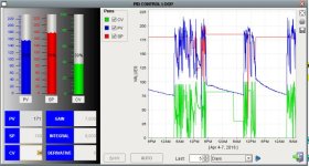
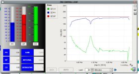
Posting a trend is always helpful. Then we can see what you are up againt. Make a trend with a step jump in the control signal is even more helpful. You could have a dead time problem where the system doesn't respond for many seconds.

Do you think there's a glitch in the controller or something with he hardware?
The SLC500 PID doesn't handle integrator wind up well and seems to only use integer math but otherwise it is sound. I NEVER understand why people want to blame the equipment that has been used 10s of thousands of time successfully when the user's system is unique.


What's your opinion? :oops:
I'm controlling temp
I would check how the counts are scaled and if the PID loop is being run at the proper interval.

I agree that feed forwards can help a lot but they shouldn't be necessary for a simple temperature control system.
 
It may help someone help you if you can post your program. There may be issues with how the PID instruction is implemented. (As Peter pointed out)

Zip the .RSS file and post here.
 
Last edited:
see if you're using TIMED or STI mode - and let us know which ...

it would be best if you could post the ENTIRE program file (RSS extension) ... we'll do the best that we can - but without seeing the ENTIRE program file we're basically guessing ...
 
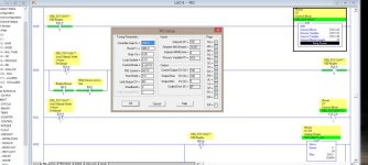
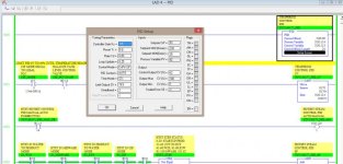
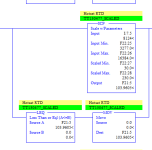
It's controlling a pasteurizer process with a heating press. I attached some images of the PID setup screen and also a trend. One that shows how the system was behaving a couple of days ago and the other of how it's currently working.
It has always given production problems. The operators have had to run the the system manually.
I also included another image of a PID setup screen of another loop which is doing the same process and it's stable. On that one I gave it engineering units of min 30 max 230 which is how I scale the RTDs. On the control loop that is not stable, when I try to give it those engineering units it doesn't work, for instance if the PV is at 186 Degrees, once I put the scaling it goes down to 2 Degrees and my error shoots up and my output is 100%. The only way I've been able to get the correct PV value on the PID setup screen is by giving it the scale I have given it which is 0-16383.
The reason that I asked if it's the hardware is because I have other control loops with the same controller that are stable which gains under 50 and so forth.
I feel like just creating a new PID instruction and starting from scratch which may seem obvious but haven't gotten a chance to do so.
I'm wondering if the reason I have to give it such high gains is because of the scaling being so high in the PID setup screen.
Also why is it that when i try to scale it to 30-230 the PV gives me the wrong value.
So far the system is running okay and the production dept is satisfied. I'm just baffled by such high gain and reset time.
Thanks all!

PID setup.jpg PID loop that works.jpg PID TREND.jpg PID TREND LAST 40 MINS.jpg RTD scale.PNG
 
Dera,
It's been a while since I've worked with SLC PID instructions but I seem to recall the instruction is expecting the Process Variable address to have a range of 0-16383, which you then scale in the instruction setup based on Smin & Smax. The Control Variable has the same 0-16383 range also. Make sure N25:145 in your example is scaled as such. This may be the source of your PV scaling issue.

It's after 5 on this end of the country & I'm heading out the door. Here's a link to a tech note which gives a bit of an explanation to newer users: https://rockwellautomation.custhelp.com/app/answers/detail/a_id/41224

Hope this helps.
 
Let me add my voice to the chorus... Post the program.

When I see PIDs like this, that have "always given problems" and have bizarre tuning constants, I check a couple things.

1) Is the loop executing at the rate it's configured for?
It says it's using STI. Is it in an STI routine? What is the value in S:30? The update time has to match. What is up with the "PID Enable" on the PID rung? This all looks VERY suspicious.

2) Is the input scaling correct?
Not just the analog 4-20ma to engineering units scaling. Is the scaling into the PID correct as well? It seems the PID is scaled 0-16383 but it is treating that range as DegF. That is very suspicious.

Post the program and we can give some constructive comments. From what you have posted, I'm of the opinion that this PID was never right to start with.
 
your "works OK" PID is located in Ladder 4 - and that PID's Time Mode is set for STI operation ... I'm just GUESSING that Ladder 4 is actually set up as an STI (Selectable Timed Interrupt) ...

your "problem" PID is located in Ladder 8 - and that PID's Time Mode is ALSO set for STI operation ...

but ...

since your system only supports one STI file, I'm GUESSING that Ladder 8 is actually NOT set up as an STI - but instead gets scanned using a JSR instruction located in your Main file ...

so ...

if my GUESSES are even close to correct, then you have a "timing/triggering" problem where your problem PID is not being "triggered" just every 0.10 second - but instead is being "triggered" on each and every scan - something more like 400 times a second ...

this type of setup throws the "time based" components (Integral and Derivative) way out of whack - and always requires some weird tuning values to compensate for the mistake ...

again - I'm just GUESSING ...

and as for the potential "scaling" issues - it's really impossible to even guess at that subject without seeing the ENTIRE program file (RSS) ...
 
Last edited:

Similar Topics

Hi everyone, Im having some questions regarding how to tune the PID for this application. It is a jacketed tank, lets say 1000 liters, and its...
Replies
17
Views
6,431
Hello I am looking for the tips and tricks of PID tunning in RsLogix 5000 V24 ladder logic programming . As I am developing logic for one of the...
Replies
2
Views
3,303
Hi I am using S7 1200 PLC . I want to use pid compact to control pressure trough manupulating the speed of motor using ACS850 vfd. The...
Replies
0
Views
1,071
Hi Experts? I am very greatful to this site who helps me on each steps but now i am stuck to tune up the PID setting of the gas turbine fuel. I...
Replies
4
Views
3,073
Hi Experts; I attached an image of pid parameters setting. When i increase the speed of gas turbine the speed goes 1% up then come back 1% down...
Replies
17
Views
4,329
Back
Top Bottom