PID Loop w/ RS500

Scot1

Member
Join Date
Mar 2016
Location
Utah
Posts
12
I have a temperature control loop that control a cooking kettle.
I bring the temperature in through a input card. I use a scaling instruction to see what degree F it is. For years I have the temperature 0-250 degrees moved into the process variable & it would read as the temperature F in the PID loop and it worked well.
Recently it stopped working. Even though the PV was being populated with the current temperature, it would not display in the PID loop.
I ended up sending the whole span from the input device. 16000 - 32767 to the Process Variable. Then it started display the temperature in the PID loop as a temperature between 0-250.
Dose anybody know why these numbers would change?
I am sure it something simple, It is magic to me right now.

Thanks,Scot
 
Sounds like it somehow started using scaling numbers in the PID block. Can you look at an old program and compare the values in the PID block. I have seen data values change before when editing the PID instruction rung, but those are usually with the firmware before 4.0
 
the BEST way to get a definite answer to your question is to post the ENTIRE program file (RSS extension) ... you'll have to zip it first - forum rule ...

you might want to post an "old" copy too - so that we can fully compare the before and after versions ...

and just for discussion, the PV (Process Variable - input signal) to your PID is SUPPOSED to be scaled from 0 to 16383 ... the PID can still work regardless of what values you feed in - but you won't get "optimum" operation if the scaling is wrong ...

and welcome to the forum ...
 
Thank you for your guys attention.
I Uploaded the 2 files you asked for in the Allen_Bradley Folder under downloads.
The old file is called "SUPER AP_MAY_16_06_old".
http://www.plcs.net/downloads/index.php?action=downloadfile&filename=SUPER AP_MAY_16_06_old.zip&directory=Allen_Bradley&

And the current file with problem is called "SAP_LINE_3_15_16_Current".
http://www.plcs.net/downloads/index..._3_15_16_Current.zip&directory=Allen_Bradley&

Look in LAD11 "CK2 TEMP" file. Rung 3. Is the PID I am working with.
I added rung 2 to make it work. This rung just converts the temperature back to the span of the sensor.
Even thought I am entering the span in the PV.
It displays as the temperature inside the PID instruction.

I am interested in what you guys think.

Thanks,
Scot
 
Last edited:
First you could have posted the zipped files as an attachment to your post. Easier to get to for those that want to help.

In the files you posted the analog input cards have not been configured, the inputs are not even enabled??
What is the analog input signal 4 to 20ma 1 to 5 volts or ?? And what does it represent in engineering units ( you mentioned 0-250 degs).

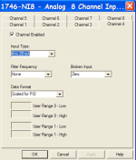
As Ron said it is best to configure your analog input for "Scaled for PID" 0-16383 to use with a PID instruction. This then becomes your Process Varible input for the PID instruction. You then use the Set Point min/max settings to scale that to your engineering units (0-250 in your case). This then allows you to enter the set point as an engineering units value.

You have the time mode for the PID instruction set for "STI" but the "STI" function is not calling ladder 11. I would set the timed mode to "Timed". Your loop update is set to .1 sec that sounds pretty fast to me, but that is your call. If you do this your tuning parameters may/will most likely need to be adjusted.

I am not not sure about all the conditions before the PID instruction, but make sure they are always true.

Edit: the file posted shows the PID instruction in the manual mode?
 
Last edited:
There is a button on the Panel view that turns this PID into auto.
I did not program this PID. But I understand it worked for years in the past.
The programmer scaled the scaling to temperature in degrees.
I am going to change the scaling.
I guess I would have to scale the set point also from degrees to 0-16383 also ??
Scot
 
If you use 0-16383 as an input to the PID's process varaible. Then set the set point min/max to the engineering unit scaling, in your case 0-250.


As Ron said it is best to configure your analog input for "Scaled for PID" 0-16383 to use with a PID instruction. This then becomes your Process Varaible input for the PID instruction. You then use the Set Point min/max settings to scale that to your engineering units (0-250 in your case). This then allows you to enter the set point as an engineering units value.
 
Mickey,

This makes most sense. I would like to still use the 0-250 for a set point.
Could you send me a two or three rung example of what your describing.
Would take the set point as 0-250 then scale it so PID sees the 0-16383 as a set point?

Scot
 
I would setup your analog input card for "Scaled For PID" this gives a raw value of 0-16383 for the full range of your input.
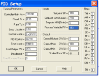
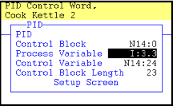
Example: (see picture)


4 ma =0 deg F=0 count
20ma = 250 deg F=16383 counts

Setting the Set MAX (Smax) and the Set Min (Smin) to 0 to 250, will scale the process variable (the 0-16383) to the engineering units set by the scaled setpoint values 0 to 250. This also allows you to enter the set point with engineering unit values 0 to 250. See picture

scaled_for_PID.png PID.png processvarible.png
 
Last edited:
Thank you,
This has helped me a whole lot.
Totally makes sense.
I probably wont have a chance to play with this for about a week. I will reply with my results.
Thanks,
Scot
 
Question:
I used the full scale for this input. 0-16383
I have a pt-100 temp sensor going through a transducer to the PLC card.
What should the span for these temperature be on these sensor?
If I put 0-250. The temperature reads too high.
 
Last edited:
I got something to add.
This PT-100 sensor reads exactly what chart says it should.
It's a 3 wire sensor that goes through a Pyromation 440 series.
Reading the spec sheet it looks like converts the 0-250 degrees F to 0-100 degrees C.
So I put 32 - 212 degrees for a span in the PID. The temperature is to high.
http://www.pyromation.com/Downloads/Man/440.pdftransmitter.
What am I going wrong?
I would attach the PLC file but am not sure how? I will drop it into the AB Downloads again.
 

Similar Topics

Hello, I am attempting to tune a PID loop on a process. The process involves a valve with electronic actuator that has quite a high deadband...
Replies
10
Views
2,187
We have a PID loop at the plant that measures our drum outlet temp. It adjusts a damper to control the temp within the set point. We have a...
Replies
8
Views
1,418
Hello All, Has anyone on here used Soft PLC brand PLCs? I've just now started doing PLC programming and I am totally stuck on trying to make a PID...
Replies
4
Views
1,553
Hello and thanks for reading my question/problem. I am working on an a application where I have a servo controlled gate that allows product (dry)...
Replies
14
Views
2,768
Hello All, I am trying to figure out the best way to control a system I am working on. I have 2 bags of peanuts being lifted up by hoist. I am...
Replies
23
Views
4,737
Back
Top Bottom