Clearly Spec'ing PLC Logic to the Programmer?

Joel777

Member
Join Date
Oct 2013
Location
Texas
Posts
4
Can you please share your experiences with best methods of how a process control system designer conveys a clear explanation of the needed PLC functionality to the person who will create the PLC program?
I've seen this done through Binary Logic Diagrams, but that ISA 5.2 standard has not been revised since 1992 and I'm guessing it's not so commonly used any more. Or is it?
SAMA diagrams look promising, but they don't seem to be widely used and may not describe all needed functionality anyway, such as interlocks and permissives, etc. Also, it may be a bit much to ask the system designer to learn a new diagram type if they've not already worked with SAMAs.
And while Control Narratives are a possibility, it may take many words to describe what could be more easily represented some other way.
How is this designer-to-PLC programmer information best conveyed these days?
 
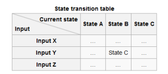
I'm not sure this is the best but for my own purposes and while mentoring young programmers in the past I've always favored finite state machines:

A Turnstile
330px-Turnstile_state_machine_colored.svg.png


Capture.PNG
 
Typically you would expect a Functional Design Specification, unfortunately this doesn't have a universal definition. Essentially this document would define the GUI requirements, the sequence control requirements (steps, transitions), interlocks, alarms, recipe parameters...etc.

I find this document to be cumbersome if it's just a word document, you just can't see the process. I prefer something based on grafcet, or a flow diagram.

A company I worked for had a pretty good system, the document along with a set of P&IDs a novice programmer (assuming they could follow the code standard) could knock out the code for an unfamiliar process rather quickly. Or at least program it to how the process engineer designed it on paper.

Ideally you should model this:
SAP-validation.jpg


This is a 30,000 foot model that you start to find in places were validation is important. There is a a whole bunch of documents that need to be crated to support this model, but at least you get a general ideal. The functional specification is where the process would be defined.
 
To expand, you need to define the process in a clear, concise way, this is a simple simple simple draft:

Code:
Step 0: INITIALIZATION
----------------------
[B]Device Activation:[/B]
    None
[B]Step Transition:[/B]
    Process Start PB Pressed

Step 1: OPEN TRANSFER ROUTE
----------------------------
[B]Device Activation:[/B]
    V101
    V102, Delay 2 sec
    V201
[B]
Step Transition:[/B]
    V101_Open AND V102_Open AND V201_Open FOR     
    Step Time = 10 sec

Step 2: BEGIN TRANSFER
----------------------------
[B]Device Activation:[/B]
    V101
    V102
    V201
    M101, Set Speed = 90 gpm
[B]
Step Transition:[/B]
    FT105.Total = Transfer_SP

Step 3: STOP TRANSFER
----------------------------
[B]Device Activation:[/B]
    V101
    V102
    V201
[B]
Step Transition:[/B]
    Step Time = 5 sec

Step 4: CLOSE ROUTE
----------------------------
[B]Device Activation:[/B]
    None
[B]
Step Transition:[/B]
    Step Time = 1 sec

Step 10: COMPLETE
----------------------------
[B]Device Activation:[/B]
    None

[B]Misc Action:
    [/B]Capture FT105.Total
[B]
Step Transition:[/B]
    Step Time = 1 sec
    (Reset to Step 0)
In my code window, it's not easy to read so grafcet/SFC/flow diagrams work better here. It provides a visual road map of the the process. But at each step, it should define exactly what devices should be activated and controlled and for how long. Now, my simple example here does not include things like interlock conditions, or enable conditions that may influence some device control. This is only for one process as well. So for each possible process in the overall system should have a clearly defined diagram. This document can grow quite large but it's much better to design on paper before going to the PLC. Plus its a medium a process engineer can take ownership of, and modify in Word/Excel/Visio to communicate the operations. Ideally, when the PLC programmer takes that document and starts to program, they update/modify it as necessary so when it's time for the FAT, the program is tested against this document to ensure the PLC programmer did what was required.
 
Last edited:
The easiest way (at least from what I have seen) is to sit down and write out the sequence of events that the machinery goes through.

give the programmer a copy and let him study the document and cad design(if there is one).

then have a meeting and discuss what's going on. a verbal discussion can bring out a lot of unanswered questions that need to be discussed later in terms of machine operation and plc programming.

james
 
Nothing or logics

I have done it both ways, no information or too much info with full logics. I like something in the middle, Basic sequence of operation to programmer, then a review with operation people, supervisors and managers. This is when the programmer and designer asks the what if questions. I always thought drawing out or writing a full set of logics a waste of time, because that is what a good programmer is for.
 
A good P&I Diagram is the best first step.

Then a loop description (control narrative) is,to me, the next step. They are a lot of work, but so is fixing a system when the programmer doesn't understand the needs.

My loop descriptions include:
- List of Input Signals
- Operator Adjustments (setpoints, gains, time delays, etc.)
- Outputs From the Loop and field devices
- Control algorithm description (PID, deadband control, feed forward, etc.)
- Alarms and Alarm Indications

How the process operates is the designer's responsibility. How to program to achieve that is the programmer's responsibility.
 
Last edited:

Similar Topics

I have seen many posts regarding start and stop using one push button but no one has explained what he is trying to do. Please whenever you write...
Replies
66
Views
24,769
Dear all, what type of built in port does fx2n-80mr plc has? i mean is it rs232, r rs422 or rs485. and which module should i use to convert to...
Replies
5
Views
114
Hi all, I was wondering if anyone had any good methods for developing functional spec / test sheets for equipment interlocks. I find the best...
Replies
3
Views
1,327
Hello PLCs.net! I've worked with servos and robotics pretty often(guess not deep enough), but I've never really specced a drive+motor combo...
Replies
5
Views
1,546
I need some boilerplate language that I can have placed in the spec that will instruct a contractor that during final signoff of their cabinet...
Replies
14
Views
3,099
Back
Top Bottom