You are using an out of date browser. It may not display this or other websites correctly.
You should upgrade or use an alternative browser.
You should upgrade or use an alternative browser.
Analog module 1746 IF4 AB
- Thread starter joaco1993
- Start date
bernie_carlton
Lifetime Supporting Member + Moderator
If the input switches were set to voltage then there won't be any problem as the voltage mode input protection is 30VDC.
If they were on current then that channel will probably be damaged as the protection shows 32ma.
The isolation to the rest of the system is only 30VDC so the inputs are not optically isolated from the backplane. Take care. If a higher voltage then you may fry more than just the card.
If they were on current then that channel will probably be damaged as the protection shows 32ma.
The isolation to the rest of the system is only 30VDC so the inputs are not optically isolated from the backplane. Take care. If a higher voltage then you may fry more than just the card.
Bernie thanks for answering, im asking because of the following:
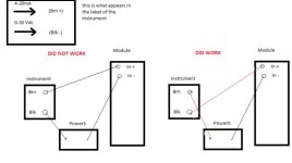
I have a level transmitter which has a label that looks like the attached img.
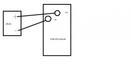
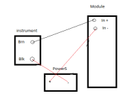
And i connected it as the image shows but didnt work, it showed a value of 12 , so I connected it the other way, see image, and then I got a reading of 20.000 which seems ok,
But i cant figure out why the second option is ok,

Mickey
Lifetime Supporting Member
The "Did not work" option is the wrong polarity on the loop powered transmitter.
Only if the level is at its upper limit and you have the module setup for current.I got a reading of 20.000 which seems ok
Mickey
Lifetime Supporting Member
Electron flow (-) minus to (+) plus.
Starting at the power supply leaving the minus side flow through the module - to + then through the transmitter - to + then back to the + side of the power supply.
Then something is wrong. Check to see how the transmitter is calibrated
4ma = 0 ?
20ma = ??
How is the analog card setup voltage or current.
Starting at the power supply leaving the minus side flow through the module - to + then through the transmitter - to + then back to the + side of the power supply.
Nope, 20.000 and it wasnt at the top, if it was at the top it should have read 32.000 and something right ?
Then something is wrong. Check to see how the transmitter is calibrated
4ma = 0 ?
20ma = ??
How is the analog card setup voltage or current.
First) you say the DID WORK solution is wired ok ?
second) The raw value for 4mA is 6000 and something and 20mA is 32000 and something
so a value os 20000 it seems ok to me..
The analog card is set to current, all channels
second) The raw value for 4mA is 6000 and something and 20mA is 32000 and something
so a value os 20000 it seems ok to me..
The analog card is set to current, all channels
Last edited:
bernie_carlton
Lifetime Supporting Member + Moderator
The names would make more sense if the sensor is used in the minus side.
Pwr source +
Module +
Module -
Sensor +
Sensor -
Pwr Source -
Or use ASF's drawing, move the sensor to the lower line while rotating it 180 degrees..
Pwr source +
Module +
Module -
Sensor +
Sensor -
Pwr Source -
Or use ASF's drawing, move the sensor to the lower line while rotating it 180 degrees..
Mickey
Lifetime Supporting Member
YesFirst) you say the DID WORK solution is wired ok ?
Those values will depend on how you have the card configured (software configuration)second) The raw value for 4mA is 6000 and something and 20mA is 32000 and something
Post your .rss file and we can take a look . Zip the file first.
Tell us which card if more then one and which channel.
Analog module 1746 IF4 AB
Are you sure this is the right catalog number?
There is a 1762-IF4 and a 1746-NI4.
Last edited:
Bernie sorry but didnt understand what you mean..
Mickey i dont have the file here but this is how i configure it:
In the IO configurations where I added the module, i set it for 4/20mA current. It is a 1746 if4. and set raw/proportional
I read in the manual that for 4 mA = 6241 and 20 mA = 31206. So if the tank is some how in the middle an input of 20000 is okay to me, why you dont think the same ??
Anyway my mainproblem is understanding the wiring, cant understand why the vendor puts 4-20mA in the brown and that cable you have to connect it to the power source and not to the input module..
Sorry if this is too basic! dont get mad! haha
Mickey
Lifetime Supporting Member
Then something is wrong. Check to see how the transmitter is calibrated
4ma = 0 ?
20ma = ??
I meant how its set up in engineering units.
I meant how its set up in engineering units.
Oh.. 4mA - 0meters
20mA-3meters
But the 20000 value is the raw input value, then I have a SCP instruction to scale the input..
Mickey
Lifetime Supporting Member
This would be ok.I read in the manual that for 4 mA = 6241 and 20 mA = 31206. So if the tank is some how in the middle an input of 20000 is okay to me, why you dont think the same ??
You said..
I read this to be 20.000ma not counts(raw data)And i connected it as the image shows but didnt work, it showed a value of 12 , so I connected it the other way, see image, and then I got a reading of 20.000 which seems ok,
Similar Topics
Hi everyone,
I have a SLC 500 (5/04) with a 1746-NI8 Analog module input.
I have two questions:
1. I have noticed there is a IN0-, IN0+ and...
- Replies
- 8
- Views
- 3,479
G'day lads,
We are using an Allen Bradley PLC slc5/03 with an analog input module 1746 ni4. we have a sensor with a response rate of 250ms. in...
- Replies
- 3
- Views
- 3,135
I am adding scale weight inputs (4-20MA) to a existing program, using analog input card (1746-NI16I- Class 3). Processor is 1747-L542C 5/04 CPU. I...
- Replies
- 7
- Views
- 8,563
HI PLC GUYS
I HAVE SOME QUESTIONS FOR THOSE WHO ARE FAMILIAR WITH ANALOG MODULE 1746-NIO4V:
1 WHAT IS THE PURPOSE OF THE TERMINALS 6 AND 9 ON...
- Replies
- 1
- Views
- 7,755
Why AMIo800 Analog input module's I/O LED is Lighting up Red?
Checked module connections, 4-20ma wires etc but this light is continuously Lighting...
- Replies
- 1
- Views
- 66


