[Logix] Any way to know when slave receives a MSG?

defcon.klaxon

Lifetime Supporting Member
Join Date
Feb 2015
Location
Far NorCal
Posts
616
I am wondering what, if anything, can be observed in a slave PLC when sending/receiving data with MSG instructions. On the master side, you have the Enable, Done, and Error bits but because the slave just sits and waits for data to show up or be requested, there's no MSG logic on the slave side. Is there any way to know on the slave side when the MSG data shows up or is requested?
 
Have the PLC sending the message send an ON bit. On the slave PLC if that bit is ON then RST a TON timer, then unlatch that bit. The timer will reset every time the slave gets a message. If the timer.ACC ever gets over 2.00 seconds then it was an old message, and ignore it, but if the timer.ACC is LES 200 (I'm assuming a 0.01 second timer base, and you could put the Preset at 200 and use the /DN) then the slave has a current message.
 
I make the first word of any data table I'm writing to a slave device a value from 0-255, incrementing by 1 every time I send it.

I use that to make a "stale data detector" in the slave device, basically "If Word0 = Word0_Old for 2 seconds, there's a comms failure".

Any approach that relies on the diagnostic counters of the serial or network port will show both the effect of online/diagnostic/HMI messages and controller-to-controller messages, so I don't use that.
 
I make the first word of any data table I'm writing to a slave device a value from 0-255, incrementing by 1 every time I send it.

OK I see what you're doing here.

I use that to make a "stale data detector" in the slave device, basically "If Word0 = Word0_Old for 2 seconds, there's a comms failure".
The logic behind this makes sense, but how does the slave know when to move the Word0 value into the Word0_old tag? I'm not entirely following how this could be accomplished. Maybe you're immediately moving it, and then comparing the value? Sorry, it's been a long week and I'm a bit scatterbrained right now.
 
Last edited:
The logic behind this makes sense, but how does the slave know when to move the Word0 value into the Word0_old tag? I'm not entirely following how this could be accomplished. Maybe you're immediately moving it, and then comparing the value? Sorry, it's been a long week and I'm a bit scatterbrained right now.

The slave moves the word0 value into word0_old on every scan, but if word0=word0_old for x amount of time, then it's a comms error, since word0 value won't change until the master is able to write to it.
 
The slave moves the word0 value into word0_old on every scan, but if word0=word0_old for x amount of time, then it's a comms error, since word0 value won't change until the master is able to write to it.

I must be missing something, sorry for just not getting this...if word0 is moved to word0_old every scan, wouldn't word0==word0_old all the time?
 
The Word_0_Old value is set to the same as Word_0 only after those two values have been evaluated to keep the timer running.

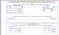
A picture's worth a thousand words; in this case the logic is in between updates to the watchdog value.

Think the logic through during the next scan when the incoming watchdog value is updated to 222:

Rung 1 the EQU condition is false, so the timer resets.
Rung 2 is false because the timer is not Done, so the latched timeout bit stays false.
Rung 3 the NEQ condition is true because the Old and New values are not equal, so the MOV instruction makes them equal.

On the next ladder scan, Rung 1 will be true and the timer starts again.

Basic_Watchdog.png
 
I must be missing something, sorry for just not getting this...if word0 is moved to word0_old every scan, wouldn't word0==word0_old all the time?

I do the almost same thing as Ken suggested, but I will let it roll over at 10000. If you write your logic in the "slave" so that the timer is enabled when the new data equals the old data and on a later (the very next branch or rung) MOV the new data value to the "old" data location, it will perform as you intend.

Order of execution is the key. It is preferable not to depend on the order of execution of rungs, but sometimes it is required to do so. I try to put things that are order dependent all on the same rung on successive branches. That way I don't come along some months or years later and accidentally screw up the order by moving a rung. I am much less likely to relocate a branch within a rung than I am to move an entire rung.
 
The Word_0_Old value is set to the same as Word_0 only after those two values have been evaluated to keep the timer running.

A picture's worth a thousand words; in this case the logic is in between updates to the watchdog value.

Think the logic through during the next scan when the incoming watchdog value is updated to 222:

Rung 1 the EQU condition is false, so the timer resets.
Rung 2 is false because the timer is not Done, so the latched timeout bit stays false.
Rung 3 the NEQ condition is true because the Old and New values are not equal, so the MOV instruction makes them equal.

On the next ladder scan, Rung 1 will be true and the timer starts again.

AH ok thanks Ken, this makes sense. You are indeed using the scan sequence to make this work; after thinking about it for a little while I wondered if that's what was going on. I will give this a shot.
 
Another thing you can do is to echo the value back to the "master" in the block of data that is being read by the master. This will tell you that not only is the slave alive and communicating, but that it is in run mode and executing the logic to copy the data.

You then would add similar timer logic in the master except you'd check for inequality to enable the TON rung.

I have seen some programs written by others that will have an extra message to read the CPU status words to determine run mode, but it can be more efficient to prove run mode simply by echoing the "MSG Count".

That's a great idea; having PLCs in remote program has got me a couple times and it would be nice to have code to check that.
 
I am wondering what, if anything, can be observed in a slave PLC when sending/receiving data with MSG instructions. On the master side, you have the Enable, Done, and Error bits but because the slave just sits and waits for data to show up or be requested, there's no MSG logic on the slave side. Is there any way to know on the slave side when the MSG data shows up or is requested?

I guess I'm a bit confused on how you have the messages setup in the first place. Wouldn't it be easier to have the master read the data it need from the slave, and conversely have the slave do a read of the master for the data it needs? The reason I ask is, I know for us poor Bubbas it can be a major PIA to track data that is being written to a controller with no clear idea of where it's coming from. This would also give the benefit of a MSG.dn bit on both sides. Or is there something I'm missing?


Will.
 

Similar Topics

I am just getting information about a need that a site has. They currently have a machine that has a ML1200 and is being interfaced to by a...
Replies
16
Views
6,632
I am having an issue with my Modbus Communications. I have a PLC 5 running a Prosoft 3100-MCM as Master. It is polling a total of 3 Devices. 2...
Replies
10
Views
5,057
Hello Guys, Please I need assistance on how to configure Powerflex 755 VSD as MASTER & SLAVE setup in Rslogix 5000 using TCP/IP network. Please...
Replies
0
Views
2,612
Hello Sir, I m new for DNP3 comunication in AB. The following things i did in my program . We are doing DNP3 slave in Micrologix 1400 channel 2...
Replies
6
Views
3,594
how to access micrologix with arduino as slave master respectively? i wanna access micrologix 1400 registers,what value used in Modbus...
Replies
1
Views
1,838
Back
Top Bottom