Crimson 3: Sending multiple Modbus commands on one button push

Bullzi

Lifetime Supporting Member
Join Date
Jun 2012
Location
Colorado
Posts
1,530
Good Morning everyone,
Working on the next phase of my Crimson Project. I need to send 4 different Modbus Commands off of one button push. I could use some ideas on how to accomplish this.

I was thinking of running a program off of the button press but I have never used a program to send Modbus Commands so I could use some help with the syntax for that. Is it even possible?

Thanks for any help you can provide.

Modbus Extended Services.jpg
 
Yes, you can do this. I would not add the code directly to the button. Write the code in a Program, and call it from the button. This will make it simpler if you later decide to run that same program under other conditions.

I also would not directly reference the device Modbus addresses in the program. You can do that, but I would create tags for these Modbus locations. This can make it easier to correct mistakes or alter other tag properties like labels and formatting in one spot rather than everywhere the tag is used.

The trickiest part to this in my opinion is going to be timing. Is the result generated by the device going to appear instantly? Do you need to wait a few milliseconds after populating the data packet before you set the command coil? Will it be persistent once you send the request? Will it hold meaningful data before you send the request?

I guess it is not really tricky, but unknown. You may not want the operator to see the result until you know it is valid, so you might have to do something to delay the visibility of the result or something along those lines.
 
Last edited:
Thanks Oki,
The trickiest part to this in my opinion is going to be timing. Is the result generated by the device going to appear instantly? Do you need to wait a few milliseconds after populating the data packet before you set the command coil? Will it be persistent once you send the request? Will it hold meaningful data before you send the request?
I am not doing a lot of control with the HMI so I am not too worried about the reply. I just want to do a remote START and STOP command to the Controller. I could use the PLC and I/O for a hardwired S/S commands but wanted to see if I can do it over Modbus.

I also would not directly reference the device Modbus addresses in the program. You can do that, but I would create tags for these Modbus locations. This can make it easier to correct mistakes or alter other tag properties like labels and formatting in one spot rather than everywhere the tag is used.
That is a excellent idea!!

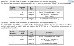
Here are the things I need to send to the controller to do a Start and Stop.

AL Start_Stop.jpg
 
I don't understand. Do you want to send commands from the HMI directly to a drive?

I'm not familiar with Crimson but surely you can just configure a modbus connection to the drive, and then build the three tags you need. When you press the button you just set those three tags to the values needed to start or stop the drive. When you change the tags in the HMI it will automatically send the new command to the drive over modbus.
 
I just love it when the Modbus values are documented in hexadecimal. I had to set up Modbus control of some Yaskawa VFDs that were like that.

Do you have one of these "Accuload III" units you can use for testing?

I think once you set up the tags for the Modbus addresses 0, 1, and 2 and get the protocol details right, it should be pretty easy to simply change the "Sub-command" tag and then write to the "coil" 4096 to initiate the command.
 
Oki,
Yes I do have a HMI and the Accuload to work with. I will start working with it tonight and see what I come up with. Thanks for the help!!
 
I played around with it last night and didn't have any luck. Could someone take a look at my program and let me know what I am doing wrong?

Where I am stuck is how to call the program and I am not sure I have the tags set up properly to send the proper value via Modbus. Any advice would be appreciated.

I noticed at least that your program sets the Start_Key internal tag, but it doesn't do anything. Was it supposed to?

Start_Cmd (not used)
Stop_Cmd (not used)
Router_Word

are all tied to the same Modbus register. Is that correct for your application?
 
maybe I'm wrong, but it looks like your program needs to write the following data:

Start
Address0 = 3 (hex 0x0003) Size of packet
Address1 = 1024 (hex 0x0400) Router word
Address2 = 6 (hex 0x0006) Sub-command

Then, force coil 4096 ON.

PacketSize, RouterWord and SubCommand should be Numeric tags
Like JHarbin found, I think you should be using Start_Cmd (not the Start_Key tag).
 
Last edited:
I am not a Modbus person, but is this right?

Modbus address 0 = register 40001 (ex. Size of packet)
Modbus address 1 = register 40002 (ex. Router word)
Modbus address 2 = register 40003 (ex. Sub-command)
 
Your program is setting the packet size to "1" when I think it should be "4".
Your program is setting the router word to "1" when I think it should be "1024" (0x0400)

Also, it appears (based on the flag symbol in the tag list) that you created the tags used by the program as flag tags but set them to be treated as integers. I think they need to be numeric tags. They are also marked as Write Only. I would change them to Read/Write and then drop them onto a page at least during the debugging stage of development.
And the last thing I see is that there is no reference (tag) for the Sub-command (400002). That is the address that determines whether the command issued is a start or a stop.

Question: Are you getting your alarm for communication? If not, then you most likely have good comms, although it still might be possible that there is a word order concern or zero vs. one based addressing issue to be wary of.
 
Last edited:
Thanks everyone,
I am playing with it now. I think were I am tripping up here is where do I set the value that is transmitted? In the Tag? If so where do I put the constant? I have put it in the Data Set Point Area. Is that correct? Or should I set it in the Program as in Router_Word = 1024?
 
Last edited:
You can set in in the same program, or maybe in a separate program that runs on startup. I think the Data Setpoint is just used to populate the tag.SP property value for use by other fields or Crimson expressions, not the tag data itself.
 
Thanks again everyone,
I got it working. The big huddle was the address offset. I had to remember that everything in the manual was off by 1 register. Once I got that though my thick head things went a lot better. It is working great now.

If anyone wants the Crimson code let me know and I will post it.
 

Similar Topics

I am trying to send AB PLC tag data using Crimson 3 on a Red Lion Data Station Plus and am having trouble. First, it appears to only allow string...
Replies
7
Views
6,953
Hey guys, hoping someone here could give me a little advice. I'm working with a CR1000-04000 in Crimson 3.1 and I was interested in adding the...
Replies
4
Views
115
Hi, I'm having an issue in crimson 3.0 when I create a programme using a case statement referencing a fault word that each bit needs to change the...
Replies
4
Views
191
How do you install update on Red Lion Crimson ver 3.1. Do I just need to run the exe file on the host server?
Replies
1
Views
107
Has anyone found a way to convert/replace/update the firmware on old Parker TS80xx series HMIs (i.e. TS8010, TS8006, etc) to accept Crimson...
Replies
0
Views
91
Back
Top Bottom