Tricky simple controller relay circuit

blackbird307

Member
Join Date
Jun 2015
Location
Winnipeg
Posts
59
I have a controller that gets turned on by the push of a momentary push button with one set of contacts, and remains on using a single SPDT non latching relay. Pressing the button again starts a sequence in the controller. After the sequence is complete the plc shuts itself off by de-energizing the relay. I am expected to make a control schematic to make this work.

I spent a few hours on this, and im stumped. I can't figure it out. The only way I can see this working is using two relays and a momentary push button with two sets of contacts. One normally open relay would be activated using one of the contacts of the push button, and would maintain itself to allow power to the controller, the other relay would have normally closed contacts which get opened when the controller completes its sequence. The other set of contacts on the push button would solely be dedicated to an input of the controller to start sequence up pressing.

Is it possible to accomplish this with using just a single SPDT relay and a momentary pushbutton with one set of contacts??? To me this seems impossible.

Controller has 4 outputs, 3 dedicated to something else. And 1 dedicated to shutting itself off. The relay is an LY1
 
Last edited:
After a little head-scratching, I sure do think you're right. Two contacts on the pushbutton, two control relays.
 
Damn it, nerd sniped again!

I've got one design worked out that *will* work, although it has a couple of caveats. Going to see if I can find a neater one before I post my answer ;)

I assume this is a purely theoretical brain teaser, and not something you're actually in the situation of having to make work?
 
Got it!

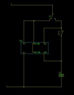
Starting position: K1 is ON. It holds itself on, which keeps power off the PLC

Press PB. K1 drops out. When PB is released, K1 remains de-energised as it has switched the 24V supply away from the PB and onto the PLC. PLC is now powered up, and stays powered up because K1 remains de-energised.

DI is a zero volts = on type, and is therefore ON due to the zero volt connection backfeeding through the relay coil and the PB.

Pressing the PB breaks this circuit, turning the input OFF. The PLC looks for this negative edge to begin the sequence.

When the sequence is complete, the PLC turns it's sourcing output ON. This energises K1.

With K1 energised, the power is removed from the PLC.

Screen Shot 2016-06-15 at 5.56.18 PM.jpg
 
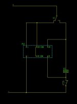
Wait, wait, better solution! Not relying on backfeeding the input any more.

Starting position: K1 is ON. It holds itself on, which keeps power off the PLC

Press PB. K1 drops out. When PB is released, K1 remains de-energised as it has switched the 24V supply away from itself and onto the PLC. PLC is now powered up, and stays powered up because K1 remains de-energised.

DI is a negative-on type, and is therefore ON while the PB is released.

Pressing the PB breaks this circuit, turning the input OFF. The PLC looks for this negative edge to begin the sequence.

When the sequence is complete, the PLC turns it's sourcing output ON. This energises K1.

K1 holds itself in. With K1 energised, the power is removed from the PLC.

Do I win a prize? :p

Screen Shot 2016-06-15 at 6.06.15 PM.jpg
 
Last edited:
Sorry to be a pessimist ASF but I doubt whether either option will work. As soon as the DO turns on to energise K1 the relay will "cut its own throat" and never actually close fully to seal itself in. The sequence will work up until that point and then the relay will just become a buzzer. Unfortunately real life relays do not work quite like PLC logic.
 
True...depending on the PLC though, I'd be optimistic that it might remain powered long enough to pull in a small relay...or if not, a suitably sized capacitor across the PLC power supply terminals should do the trick :)
 
If it's acceptable to hold the pushbutton down until the PLC is up and running this should work.
Since there are so few I/O I assume it's very small so it probably starts up in an instant.

OP didn't say but I'm assuming the controller has source outputs.

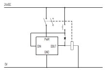
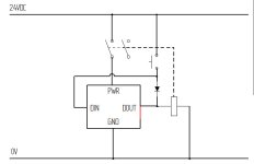
Sorry about the funky schematic but I'm sure you can understand it.

You could add another diode directly on DOUT for additional protection but it should not be needed.

PS. If it's not obvious the controller should set the digital output (DOUT) immediately on start up.
Digital input (DIN) will read 24V when the button is pressed (and nothing when it's not pressed thanks to the diode).
To power off just set the DOUT to 0.

circuit.jpg
 
Last edited:
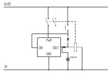
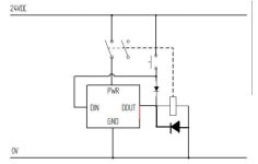
If you wanted feedback for the user so he'd know when the system was up and running, you could do this:

circuit2.jpg
 
Pete S: IS PWR wire (relay contact)connected to horizontal wire coming from union between Push Button and diode ?. Otherwise is not going to work.
 
Last edited:
Pete S: IS PWR wire (relay contact)connected to horizontal wire coming from union between Push Button and diode ?. Otherwise is not going to work.

I updated the schematics to make it clearer.

When you press the button it will energize the relay coil. The relay contacts will then power up the controller. When the controller is powered up it also energizes the relay and the user don't have to push the button anymore.

A diode is a one way valve for current. Current can only pass the way the arrow points and not the other direction.
This means that the digital in (DIN) can sense when the user pushes the button the second time even if DOUT is at 24V.

A typical diode is the 1N4148. https://en.wikipedia.org/wiki/1N4148
They cost nothing. All you need is to make sure the diode can handle the current passing though it. So depending on the relay coil you might need something a tiny bit bigger.

circuit-clarified.jpg
 
Last edited:

Similar Topics

Good Eve Gentlemen, We had this cold room which was converted to hot room before I joined this work. Everthing was fine until a month ago, they...
Replies
9
Views
2,096
Hi Here's a question I'm about to ask Omron.. as soon as I can figure out who to ask.. It's complicated asking support.. their web email form...
Replies
2
Views
3,112
Hi all, I am just out of school and working in my first engineering position doing mostly PLC (SLC500) work at a small company. I have been...
Replies
11
Views
3,572
We have faced a tricky problem . The panel view Plus 1000 is not going online..The network guy "Ping" from system and shows that the node is ok...
Replies
4
Views
2,216
Hi guys, Simple question, but I cannot find simple answer to it: How to read the instance DB symbolic name from within FB? If this is not clear...
Replies
7
Views
2,543
Back
Top Bottom