Matching inputs and outputs based on time / pulses? (Not sure how to word this)

Brandon_K

Member
Join Date
Mar 2016
Location
Pittsburgh, PA
Posts
150
I have a scenario (it's a game) where the player has a dozen phone jacks (think 1/4" headphone, not telephone) and a half dozen patch cables that they have to patch in the correct order to win.

IE, J1 to J7, J2 to J10, J3 to J6 and so on.

The first design of the game was simply done in wire logic where the jacks were wired (in an incredibly odd fashion) basically as a long series switch. That switch closed the terminals on a microcontroller (think Arduino) that when the circuit was made for more than 1500ms, the player won.

The issue with phone jacks is that certain components "make" when they shouldn't as it's an inline axial connector. IE, in a TRS (tip, ring, sleeve) style connector, the tip of the plug will make with the sleeve and ring on insertion. This allows players to "cheat" the game, usually unintentionally. They're simply slow on the insertion, which if they get lucky and they start on the correct jack, can trigger an immediate win (or as immediate as 1500ms).

A different style of connector, like an XLR would solve the problem as all three conductors make / break at the same time due to it's staggered configuration, but I cannot source a supplier for the patch cables that we need. Otherwise, this could all easily be done in wire logic.

So I began thinking about implementing a PLC into the mix. My thoughts were to have an series of outputs do nothing but pulse off / on at a given rate, IE 50ms, 75ms, 100ms, etc on up the line. The input would only go true if it saw it's mate. IE, Y1 flashes at 50ms, X1 is looking for a 50ms pulse. If X1 sees a 50ms pulse, it goes true. If it sees a 75ms pulse, it does nothing.

The Click PLC's that we use in a large portion of our games have the ability to change the input to a pulse catch, filter or an interrupt. Filter is the closest to what I want, but it only functions as equal-to-or-greater-than and that does me no good.

Thoughts?
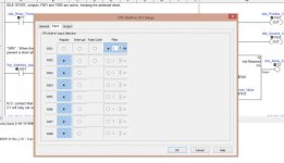
Click-filter-input.jpg
 
Does the Click do a millisecond timer? It's been too long since I've used one. Otherwise use a counter that increments every scan.

If it does, just create a free-running timer that self resets after a second and then restarts. Use the accumulated value in a compare (think Limit or a GT, LT pair).
 
It can be done with an arduino for very low money, however it also can be done with an Click unit as long as it has enough I/O

first a question:
would you like to have all possibilities like 0 to 1, 2 to 4, meaning you can stick them anywhere,
or do you have a row of cables and a row of connectors and you can put a cable in a jack.

if the last one you can use: set an output and check all inputs, then set next output and go on.

if its a mix every output is also connected to an input, and you can do the same
set Y0 and check if for any X is on.
No need for pulses etc.
You can use any type of connector btw.

with arduino it can be made much faster, and more versatile, and cheaper.
As this is not an arduino site, better do this on arduino.cc (if you do put your name rootboy in the message so i can find you.
On arduino you can put a resistor in the jack and use a resistorbridge,
with three connections you can make about 500 different codes.
this way you dont need any loose cables just a patchboard.
even a old switch has for example 24 gates in RJ45, nice cheap, and make some plugs with resistors in it.
With RJ45 as there are 8 pins you can have 127 different codes even without resistors.
 
Does the Click do a millisecond timer? It's been too long since I've used one. Otherwise use a counter that increments every scan.

If it does, just create a free-running timer that self resets after a second and then restarts. Use the accumulated value in a compare (think Limit or a GT, LT pair).

Yeah, it will do ms timers no problem. Unless I'm missing something, if I do an accumulating counter and compare, that would work on any input. I need to differentiate inputs in some fashion. The only way I can think to do it would be to have X1 specifically looking for a 50ms (or whatever value) flash / pulse, X2 looking for 75ms, etc.

It can be done with an arduino for very low money, however it also can be done with an Click unit as long as it has enough I/O

first a question:
would you like to have all possibilities like 0 to 1, 2 to 4, meaning you can stick them anywhere,
or do you have a row of cables and a row of connectors and you can put a cable in a jack.

if the last one you can use: set an output and check all inputs, then set next output and go on.

if its a mix every output is also connected to an input, and you can do the same
set Y0 and check if for any X is on.
No need for pulses etc.
You can use any type of connector btw.

with arduino it can be made much faster, and more versatile, and cheaper.
As this is not an arduino site, better do this on arduino.cc (if you do put your name rootboy in the message so i can find you.
On arduino you can put a resistor in the jack and use a resistorbridge,
with three connections you can make about 500 different codes.
this way you dont need any loose cables just a patchboard.
even a old switch has for example 24 gates in RJ45, nice cheap, and make some plugs with resistors in it.
With RJ45 as there are 8 pins you can have 127 different codes even without resistors.

if the click has analog input you can do it also on the click. btw.


They need to be differentiated, meaning only Jack1 will trigger X1, only Jack2 will trigger X2, etc.

We are staying away from Arduino's. We've used them, had numerous issues. The second a customer sees a Arduino in a product, that immediately cheapens it. Additionally, they see Arduino and if there is a problem it's immediately "The Arduino went bad! Send me another one!".

Plus, by the time you spend the money to protect the Arduino, you've bought yourself a Click (or better). I recently saw a project using "Industrial Shields" and the money spent on a (IMO, hacked together) system, could have bought a very nice Productivity 2000, Do-More or DL06 system. The only reason why the Arudino system was put in place was because the programmer doesn't want to learn ladder.
 
http://accautomation.ca/building-a-plc-program-that-you-can-be-proud-of-part-5/

The above link shows a game of simon using a Do-More PLC and AdvancedHMI. Some parts may be applied to your project.

If you are looking for a sequence that the wires are plugged in then it would be similar.

I agree with you on the outputs. Have each of the six outputs continually pulsing. Monitor the input to see the timing of the pulse to determine what wire was connected.

Regards,

I'm not worried about the sequence, that part I have down. But this particular game doesn't need to be a sequence as much as it just needs to see X1 - X6 as complete (but differentiated) circuits.

How would you go about having the input monitor \ match an output? It may very well be possible the Click simply doesn't have an instruction to look for a specific interval on the input. I'm just not sure how to recreate the lack of instruction, in ladder, if it's even possible.

Maybe I'm missing something, but couldn't you just turn the outputs on one at a time and look for the proper input to turn on? You could cycle through the outputs at something like 50ms or less. Just enough time to see if an input turned on (plus whatever settling time you deem necessary). I don't see any big benefit in detecting proper pairings in parallel (all at once) when it would be so much simpler to detect proper pairings one output at a time at a rate that would be similar or faster than your original model. Brian
 
Maybe I'm missing something, but couldn't you just turn the outputs on one at a time and look for the proper input to turn on? You could cycle through the outputs at something like 50ms or less. Just enough time to see if an input turned on (plus whatever settling time you deem necessary). I don't see any big benefit in detecting proper pairings in parallel (all at once) when it would be so much simpler to detect proper pairings one output at a time at a rate that would be similar or faster than your original model. Brian

Because it is a game, literally. The player needs to figure out what order the patch cables have to go in. The winning "combination" would be something like;

J1 to J7
J2 to J10
J3 to J8
J4 to J5
J6 to J12
J9 to J11

The "input" of J1 would come from the pulsing output of Y1, signal travels to the jack, over the patch cable (that the player has inserted) to J7, out of J7 to X1.

With your suggestion, they could patch J1 to J10 and still have a complete circuit, which we don't want. We need them to plug in the 6 patch cables to specific jacks.

Perhaps I didn't make myself clear. Here's my assumptions:
Jacks listed on the left of your list connected to input 1-6
Jacks listed on the right of your list connected to output 1-6
All jack combinations are 1 input to 1 output.

My recommendation:
Step one: turn on output 1 (connected to jack 7), check to see if input 1 (connected to jack 1) turns on, record a pass/fail for this pair.
Step two: turn off output 1, turn on output 2 (connected to jack 10), check to see if input 2 turns on record a pass/fail for this pair. ...
Final step: if all check steps pass, the puzzle is solved. The key is only checking to see if the matching input turns on when the relevant output is on. You need to ignore the non-relevant inputs.

In the example you give for an incorrect pairing, when output 1 turns on, input one does not come on and registers as a fail for that pairing.
When output 2 comes on, input 1 comes on, but is ignored. Input 2 does not turn on and registers as a fail for that pairing.
Brian
 
Last edited:
Ok, see if I understand correctly. You have 12 jacks J1-12. Each of these jacks is wired to an input and an output. The goal is to match a pattern of connections made by 6 cables. Is there any feedback to the player? Is it simply, "you win" when they are all correct?

If this is correct, I agree with Brian123. It can be done very easily by turning on one output at a time to determine where the other end of that cable is connected. Each time you turn on an output, 2 inputs will come on. Just latch this status and move to the next output. You can do this so quickly that it will appear instantaneous.

Using your example,
Turn on output 1, see that input 1 and input 7 come on, store 7 into register 1.
Turn on output 2, see that input 2 and input 10 come on, store 10 into register 2.
Turn on output 3, see that input 3 and input 8 come on, store 8 into register 3.
Turn on output 4, see that input 4 and input 5 come on, store 5 into register 4.
Turn on output 5, see that input 5 and input 4 come on, store 4 into register 5.
Turn on output 6, see that input 6 and input 12 come on, store 12 into register 6.
Turn on output 7, see that input 7 and input 1 come on, store 1 into register 7.
Turn on output 8, see that input 8 and input 3 come on, store 3 into register 8.
Turn on output 9, see that input 9 and input 11 come on, store 11 into register 9.
Turn on output 10, see that input 10 and input 2 come on, store 2 into register 10.
Turn on output 11, see that input 11 and input 9 come on, store 9 into register 11.
Turn on output 12, see that input 12 and input 6 come on, store 6 into register 12.

The outputs are turned on in sequence one at a time, the data pattern in registers 1-12 has the solution from both ends of the cable. When this pattern matches the "winning" pattern, the game is over. Each output only has to be on for one scan. If your scan is 20ms, the entire thing is done about 4 times a second.
 
Perhaps I didn't make myself clear. Here's my assumptions:
Jacks listed on the left of your list connected to input 1-6
Jacks listed on the right of your list connected to output 1-6
All jack combinations are 1 input to 1 output.

My recommendation:
Step one: turn on output 1 (connected to jack 7), check to see if input 1 (connected to jack 1) turns on, record a pass/fail for this pair.
Step two: turn off output 1, turn on output 2 (connected to jack 10), check to see if input 2 turns on record a pass/fail for this pair. ...
Final step: if all check steps pass, the puzzle is solved. The key is only checking to see if the matching input turns on when the relevant output is on. You need to ignore the non-relevant inputs.

In the example you give for an incorrect pairing, when output 1 turns on, input one does not come on and registers as a fail for that pairing.
When output 2 comes on, input 1 comes on, but is ignored. Input 2 does not turn on and registers as a fail for that pairing.
Brian

Hmm. I follow now. That's interesting. Not sure how to write the ladder, but I'll give it a go later today. Thanks for the explanation.
 
It seems to me the game as I described it is not very "fun". It's mostly frustrating. It needs some feedback, but not too much or it becomes easy. Perhaps instead of evaluating constantly, it only checks the cables every 10 seconds and reports how many are correct. Not which ones are correct, just a total correct. The total number of permutations is pretty high (10,395 if my calcs are correct). With no feedback, I think I would find something else to do pretty quick.

Report total correct only when all 6 cables are connected is probably even better.
 
Last edited:
It seems to me the game as I described it is not very "fun". It's mostly frustrating. It needs some feedback, but not too much or it becomes easy. Perhaps instead of evaluating constantly, it only checks the cables every 10 seconds and reports how many are correct. Not which ones are correct, just a total correct. The total number of permutations is pretty high (10,395 if my calcs are correct). With no feedback, I think I would find something else to do pretty quick.

Report total correct only when all 6 cables are connected is probably even better.

There is feedback, I just never explained the entire game. The patch cable game is just one "mini game" that is part of a 5 game "bomb" prop. You have to do some math, flip some switches in the right order, do a few pushbuttons on the HMI, patch cable game as well as a 10 digit keypad that you have to find and enter the correct combination.

I'll post some pictures of it when it's done if there is any interest.
 
I attached a quick attempt at a Click program to do what you want. I'm not sure if it is functional, I don't have one to test, and I've never actually worked with Clicks before. :)

Brian
 

Similar Topics

sir, while running program in codsys an error occur 'C0138: No matching 'FB_Init' method found for instantiation of FbPowerPlantControl.' how to...
Replies
1
Views
72
After great help on the forum getting a Red Lion G3 HMI to control & communicate with Advantech's ADAM-4055 D/IO modules, the next step was to...
Replies
15
Views
4,345
Hello. I have a Power Flex 755 that is pulling material (fpm) across conveyor rollers that are controlled by a Powerflex 525 (rpm). I am probably...
Replies
17
Views
4,878
I have a 1771-IFE/C analog card where the data that is showing in the I/O config is not matching what is the actual register that the data is...
Replies
2
Views
1,430
I'm running a PLC simulation software and I have a client Qt, I get the data which is a temperature from the PLC and it's running its own internal...
Replies
4
Views
1,662
Back
Top Bottom