Advanced Control: Tank Level

Join Date
Apr 2002
Location
No income tax, no capital gains tax. Freedom!
Posts
8,389
Oh No! Not that again!
I will start out sort of simple ( evil thoughts )

Suppose I have a tank that is 4 meters tall with a constant surface area of 1 square meter. There is a pump with a capacity to pump 1 cubic meters per minute and the pump is controlling the outflow. Assume the pump responds quickly so the pumps response time is 0. The motor speed and pump flow responds linearly to control signals between 0 and 100%.

There is no in flow......for now. ( evil laugh )

The set point is set for 1 meter and the level is now 2 meters. The control is a dirt simple proportional band where the pump stops at 1 meter and is on 100% at 3 meters.

If the level happens to be at 3 meters and no other fluid is added, how long will it take for the fluid level take to get to 1 meter. The control is still the same.

Get out your Excel spread sheets.
If you know the answer the PM me.
 
I want to try to figure this out, but what do you mean by "constant surface area" of the tank? Obviously we need to figure out the shape of it to calculate, i'm just not sure what you mean.
 
Since he specified a constant surface area, you don't really need to know the shape. He means that no matter how full the tank is, the area at the surface of the fluid is one sq. meter.
 
Good, MK42 first then JordanCClark mentioned Zeno's paradox. Your answers are correct given the assumption you both made. A mathematician would say the level approaches 1 as time goes to infinity but we don't have all day.

New requirement. Given everything else is the same how long does it take to get within 1% of the SP at 1 meter. That means how long does it take to go from 2 meters to 1.01 meters and 3 meters to 1.02 meters.

Rupej, assume the tank is a vertical cylinder. JordanCClark is right the shape doesn't really matter as long as the surface area is constant. The fact the surface area is constant makes this problem much easier to solve. If the tank was a horizontal cylinder then the calculations get to be much more messy because the surface are of the tank is maximum when the tank is half full. If the tank had a funnel shape section that would also make calculations much more difficult. I want to use relatively simple problems to start with.

There are rules of thumb that I learned long ago that make solving these simple cases trivial. I will share them after the forum after people show a good effort to get the answers. Meanwhile suffer through the math and physics guys. ( evil laugh ).
 
NK42 got the right answer. At least it is close enough if not exact. I will wait for more solutions or guesses before I work out the exact answer.

I have a feeling that MK42 worked out the exact solution using calculus which is how I would solve the problem but if I didn't have a computer or calculator I could get the same answer give or take a few seconds.

MK42 has done well the best so far.

There is more to come though.
 
To get an approximate solution is not too hard if you remember what a time constant is and that it takes 5 time constants to get within 1% of the final value or SP. Most texts and instructors will say it is the time it takes a response to go 63% of the way to the final value. That is true if you can measure the response and everything is perfect but there is a better way of saying what a time "constant" is. A time "constant" is the something divided by the rate of change in something. In the first example the tank level error is 1 cubic meter. At a level of 1 meter the pump is at 50% of flow or 1/2 cubic meter per minute so the time "constant" is 1 cubic meter/(1/2 cubic meters per minute or 2 minutes. We get the same result when the level is at 3 meters so the error volume is 2 cubic meters. Since there is 100% flow at 2 meters of error the flow will be 1 cubit meter per minute. This also results in a time constant of 2 minutes. Engineers will use different numbers of time "constants" depending on how accurate they want to be. Some use 4 time "constants" to be within 2% of the final value and some use 5 time "constants" for the time it takes to get withing 1%. Of course MK42 has the exact answer but I bet he hard to think about it.

Notice that I have put quotes around the word "constants". I do this because in reality the time "constants" may not be constant using my definition. If you use the text book definition you can get into trouble or have difficulties tuning the system.

What would make the time "constant" change as a function of level?
I am a betting that MK42 can figure it out.

Oh by the way the equation is
Level(t)=(SP+(PV-SP)exp(-(PV-SP)*A*t/(PV-SP)*Kp))
SP is the set point. As time goes to infinity the exp() function will go to 0 leaving on the SP.
At time=0 the level is equal to the SP+(PV-SP)*1 because the exp function is 1. This simplifies down to just the PV. The argument of the exp() must be negative if it is to decay to 0. (PV-SP)*A is the error expressed in volume where A is the surface area of the tank. (PV-SP)*Kp is the pump flow or rate of change in volume. I could have re-written this equation in terms of level so the time constant is the error in level divided by the rate of change in level. MK42, give others a chance.
 
I'm a little late to the show

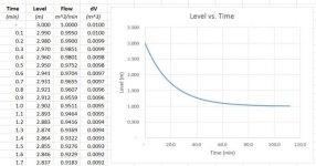
I didn't have a lot of time to look at this when you posted but since you mentioned spreadsheet in the initial post here the one I made. I took time steps of 0.1 minutes, calculated the flow for each time step, calculated the change in volume for the time step and then subtracted this change to get a new level. In the graph you can see the exponential decay even with this coarse resolution.

attachment.php


LevelCurve.jpg
 
Oops, almost forgot this thread

One of the points I wanted to make is that time constants aren't always constant. Especially when systems are non-linear. Tank level control is simple and usually doesn't require precise level control but there are plenty of applications where time constants aren't constant and tank level control is one of them.

So how can a time constant not be constant? Easy. You need to remember my better definition of what a time constant is. A time constant is something divided by the rate of change in something. In the tank level control example the tank has a constant surface area but what if the tank was horizontal? Now the rate at which the level changes is dependent not only on the error but the changing surface area of the fluid as the level goes up and down. This isn't too much of a problem if the fluid level doesn't change much but I have seen threads here where people were trying to control the level in a pond or small lake. I bet the sides were sloped so the surface area changes a lot with the level. In this case knowing how the level error changes as a function of the rate of level error changes can be useful. We have seen there are formulas for setting the integrator time constant in a PID to the time constant of the open loop system being controlled. If the time constant in the open loop system changes during operation then the integrator time constant should also change. This means gains may need to change on-the-fly during operation.

Oh yes, the gain may need to change too because the gain of a tank and pump system is the rate of level change to out flow in this case. Obviously in the simple example it is 1 cubic meter per minute divided by 1 square meter or 1 meter per minute but if the surface area of the tank changes then obviously the gain will change too.

Be thankful if the fluid surface area of the tank is constant. Be wary if the fluid surface area of the tank varies if you need precise control. Otherwise simply do what rupej suggested in another thread an simply use a proportional band. Even if the valve and tank are not linear it won't make that much difference because the closed loop system will not oscillate or over shoot.
 
Great thread- I haven't had a chance to try crunching the numbers but I appreciate the thought-provoking points. Thanks!
 
Wait, I am not done yet. Not by a long shot.
What if the pump capacity was 10 or 100 cubic meters per minute?
What if the the proportional band was changed to 0.1 meter instead of 2 meters? That is effectively change the proportional gain. Will the system oscillate due to the proportional gain being too high?

A design engineer needs to know the answer to these questions. If the tank level can be maintained do a band of 1 meter to 1.1 meters then 2 meter high tank will be good enough. That reduces the size and perhaps the cost by by almost 1/2.
 

Similar Topics

This video shows the things I think about on page 1. I use Laplace transforms a lot. Laplace transforms allow one to express differential...
Replies
2
Views
1,806
The purpose of this thread is to use a simple system to show how one can approach systems that are much more complicated. Everyone knows...
Replies
22
Views
12,279
Is anyone interested in covering this topic at a college level? Tank level control is a simple application but I can go where most have not gone...
Replies
26
Views
6,541
Instead of this info getting lost in another thread I will start a new thread. For those that don't know you can search for Advanced Control on...
Replies
8
Views
2,650
sampling data. I will probably use this in a magazine article.
Replies
18
Views
8,382
Back
Top Bottom