MicroLogix 1000 - Half the outputs don't work

Join Date
Jul 2016
Location
Michigan
Posts
4
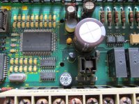
Hi all. I am a student and recently bought a used Micrologix 1000 L32BWA PLC with known bad outputs to help further my education. Outputs 6-11 work fine but outputs 0-5 do not. I am ok learning on a plc with only 6 outputs but was wondering how difficult it would be to troubleshoot and repair the faulty outputs. The status lights of the faulty outputs come on but I do not hear the relays for outputs 0-5 "click" when they are turned on, thus no continuity exists between VDC and each of the outputs 0-5. Could this be because of bad relays or does the problem exist somewhere else in the circuit? Any advice would be appreciated. Thank you in advance! Nate
 
Welcome to the forum!

It's a pure guess on my part, but if 6 sequential outputs are ALL bad, then I'd say it's unlikely to be in the relay itself. More likely to be somewhere further "upstream", and much harder to fix.

That being said, you've got nothing to lose by taking it apart and having a look, seeing if you can spot any obvious burn marks or dirty solder joints.

If you want to expand your skills further, I'd investigate a MicroLogix 1100. You can still use the free software, plus you get ethernet onboard.

If you want to throw a bit (or a lot) of real money at it, get yourself a 1769-L16ER-BB1B and teach yourself RSLogix 5000 (or Logix Designer as it's now called).
 
Thank you very much for your reply ASF. That is kind of what I was suspecting. I poked around with a voltmeter inside but was unable to conclude anything or see any burn marks. Also thanks for the recommendation for the micrologix 1100, I just may go that route being it is much cheaper than the 1769-L16ER-BB1B and being a student, I do not have the funds. I would love to learn the RSLogix 5000 software however. Once again thank you ASF. Your advice is greatly appreciated.
 
From your description, I would look at the manual for output fusing.
For a 16 point output module, there is a main fuse, and (2) secondary fuses (1) for outputs 0-7 and (1) for outputs 8-15.
I suspect that there may be a blown fuse, but that's a guess on my part.

james
 
Buy a $70 new click PLC from Automation Direct to learn on and don't waste your time with bad outputs which may not be fixable to to physical damage to the circuit board or silicon.
Messing with broken stuff is a huge waste of your time and not worth it.
If you want AB you can get a good Micrologix 1400 for $150 on ebay.
 
No problem! Yes, it is a huge amount cheaper, that's for sure, few people can afford a compact logix and studio 5000 just for training purposes unfortunately!

Good luck with your learning, hopefully we'll see you around here some more!
 
Here are some suggestions. If you feel comfortable poking around inside, the 1st thing I would check, with the power off, is the continuity of the relays power return buss. to do this, you are going to have to identify which 2 pins on each relay are for the coil. To help you find them, all six of the relays should have a certain pin connected together. You should find just about zero resistance between that point and the same point of the 2nd group of 6. If that checks OK, then write a test program that turns on all the outputs and check the voltage across each output relay coil. The voltage should be the same for each coil. Next, if that checks OK, then, check the resistance of ech coil and they should be about equal. If they are not, the coils themselves have failed. If they are all about equal, the contacts are probably welded together on each of those 6 relays because you cannot hear the "click".
 
Last edited:
First of all, thanks for all the responses. I have poked around and have determined that all of the relays are functioning (even the bad ones) by externally applying 24v across the red and pink pins depicted below in the image. I can hear the click of each relay when I do. However I uploaded a test program as mentioned to fire all the outputs and measured 24V between the red and yellow pins for the working outputs and 0V between the red and pink pins for the faulty outputs. Having determined the bad output relays can still "click" the problem must be upstream or in the component with the pink circles. Am I out of luck?
 
I am saying this just in case this link wire has been missed'

You must have a supply wire hooked to VAC0 , also another supply hooked to VAC1 ,

and again a supply to VAC2 plus also VAC3 and VAC4 even if they are from the same supply

They allow the outputs OUT0 OUT1 OUT2 OUT3 OUT4 OUT5 onto out11 ,
in order for them to work when their relays pull in. (CLICKs)
 
When you check and get 0V across the relays not firing, check from one side of a bad relay to the other side of a good relay. Do this for both the 24V and 0V sides. It may be something as simple as a bad 0V trace not getting to some relays, or bad 24V trace going to the bank of control transistors.
 
I think I may have found the issue. Could there be a missing IC chip indicated by the red outlined area? I tested the continuity between each of the blue dotted pins of the IC below it (it may be hard to see in the image) and the 0V side of the each relay and continuity exists. So each blue dot connects to a 0V pin of one of the working relay outputs (6-11). However within the red outlined area each orange dot connects to the 0V side of relays 0-5 which do not work. I bought the plc used but it seems strange for a IC chip like that to be removed. On top of the IC that is there is TD748A1 62305AFG. I did a google search and it seems like a rare component. I will keep searching and try soldering the ic if I can buy one. Thank you all for your suggestions to keep me trying to solve this.

 
Your picture I believe shows that yours ML1000 is A 1761 -L32BWA
Which is 110v ac power supply .

A 1761 -L32BWB has a 24volt dc power supply
That pretty much explains the diffences between the two photo,s except yours is missing the surface mount IC

On your photo it appears that the IC has alway been missing as those solder pads are
extremely tiny and easily damaged so how did it get removed so cleanly
 

Similar Topics

I have a customer that was troubleshooting an issue with communication loss with a PanelView and MicroLogix 1000, I think they were just trying...
Replies
6
Views
5,857
Hi all i need some information regarding micrologix 1000 half duplex comunication . i am using l16BWA micrologix 1000 . i have changed the channel...
Replies
2
Views
3,584
Hello all. I was attempting to use half duplex with a micrologix 1000, and now rslinx cannot find the processor. I was hoping someone who has...
Replies
4
Views
3,482
"Hello! Good day! Excuse me, I have a question regarding the 1761-NET-ENI. RSLinx has already detected it but it's not connecting to the PLC...
Replies
4
Views
126
Hi all, We have a very old pit pump system running on Micrologix 1000. Now, whenever there is an alarm for high conductivity, we want that alarm...
Replies
5
Views
1,255
Back
Top Bottom