You are using an out of date browser. It may not display this or other websites correctly.
You should upgrade or use an alternative browser.
You should upgrade or use an alternative browser.
PID tuning for Oven Temperature
- Thread starter michaeli
- Start date
Have a look at this thread...Enjoy
http://www.plctalk.net/qanda/showthread.php?t=4619&highlight=sliding
HTH
http://www.plctalk.net/qanda/showthread.php?t=4619&highlight=sliding
HTH
Peter Nachtwey
Member
michaeli, can you post a .txt or .csv file that has 3 columns. Time, Control Output and PV?
What you need first is a model that consists of a gain, one or two time constants and a dead time. From that the PID gains can be calculated.
What makes your system tough is the dead time. When the dead time is long it is time to use a Smith Predictor.
Other things that can affect oven performance is variance in the load. If the product is moving through the oven on a conveyor then the rate at which product is moving through the oven makes a difference. The is no specified in your .jpg files.
The Z-N method is a joke. Look at the www.controlguru.com site.
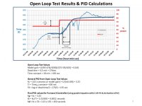
Below are some tuning results based on your open-loop test and first order plus deadtime model assumption (process gain = 0.106, dead time = 270 seconds, time constant = 630 seconds). Controller gains assume the ISA PID structure (AB PLC5 implementation) and use of the SIMC tuning rules as described by Skogestad and Grimholt (http://www.nt.ntnu.no/users/skoge/publications/2013/grimholt-dycops/0122.pdf).
PID gain = 12.6 (assumes simc tuning parameter = deadtime)
Integral term = 12 minutes/repeat
Derivative term = 1.3 minutes per repeat
(remember to observe the scaling required when entering the PLC5 parameters if using an integral control block)
Less aggressive tuning is had with a PID gain of 10 (simc tuning parameter = 1.5 * deadtime).
If you try these, I'd like to hear if it's any good. A couple of concerns I have are any noise on the measurement signal (should be filtered out if present) and the low (.25 degree temperature) resolution of the input signal (1000/4095).
Good luck!
Peter Nachtwey
Member
A derivative gain and the filter are not necessary. The open loop system has only one pole so so only one gain other than the integrator is required. The integrator has its own pole. So the final closed loop system will have two gains and two poles. There is no need for a 3rd poles despite what that stupid pdf says.
Eq 10 in the pdf is correct. It is the same formula for the controller gain that both the controlguru guys and I would compute. The other tables of gains and time constants is determined by trial and error using the IAE method to find optimal gains. However, this method depends on the steps being ONLY 1. If the steps are changed to 2 the optimal gains are different. That isn't right.
If the OP would provide a .csv or .txt file of time, control output and temperature I could compute a better second order plus dead time model and more accurate gains.
A SOPDT model assumes there are 2 poles. NOW a derivative term is required.
Here is an auto tuner written in Scilab with examples. One guy on LinkedIn used it and it worked for him so he wrote the user interface. One day I would convert it to python
http://deltamotion.com/peter/Scilab/AutoTune/
pid tuning for oven temperature
BoB/Peter/James
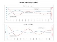
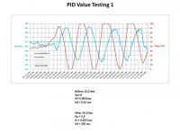
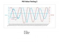
thanks for your feedback on this. reviewing all the information now and will update again. posting now with just xls files as got error for posting in csv format. first is for open loop. second file is for testing of new pid values based on the open loop testing with Kp;Ki;Kd changing from 6;0.003/sec;.01sec to 2.9;0.007/sec;282sec at 10:17am.
oven control system is using a plc5 with independent PID and PD blocks. suggested values of PID gain = 12.6 (assumes simc tuning parameter = deadtime), Integral term = 12 minutes/repeat, Derivative term = 1.3 minutes per repeat. this would translate to values needed of Kp = 12.6, Ki = 0.0014/sec and Kd = 78 seconds?
Peter Nachtwey
Member
I don't use Excel. How do I convert the time in column A to minutes in Excel? I need the time to start at 0 and increment by minutes or fractions of minutes. The hours and AM are useless.
Michaeli, if you increase the rate of material going though the oven or furnace then the control output will net to be increased. A feed forward may be needed because the integrator time constant may be too slow to adapt in a reasonable amount of time.
cjd1964, the is a lot of videos on control theory on YouTube. The problem is that much of it is useless which is why people still tweak gains. I am in the process of making some videos "Peter Ponders PID". The first video I slam someone that is teaching about root locus.
https://youtu.be/uYhz3TuTkfM
It is a use technique that fills students minds up with useless ****. I show a better way but at the end I slam the control theory teachers because they provide the transfer functions when the big challenge is doing what we are doing here, identifying the system.
Here is a video about the basics of system identification. There are only two parameters to identify so I can show graphically what is happening with a 3D plot.
https://www.youtube.com/watch?v=qzr6eL90Aok
Here is an example of the basic technique used to tune a motor with a gain and time constant just like in the example. The only difference is that in the video I add an offset for a control output null because in real systems a control output of 0 doesn't always result in 0 speed.
Then I go back to the example in the root locus video and show how to do system identification when there are 4 parameter to identify. The teachers should show the students how to do this FIRST. Then the students will know where the transfer functions come from. I added a little reality with noise and truncation ( quantizing ) due to limited feed back resolution. Still the system identification works.
https://www.youtube.com/watch?v=lermULNDz3M
I can look at Michaeli's open loop response and tell right away it really should use a SOPDT ( second order plus dead time ) model so Michaeli's plant needs to have a plant gain, two time constants and a dead time identified. The control will need to be a PID.
The document Jamesau posted a link to only covers FOPDT systems. I have formulas for tuning SOPDT system but like I said in the video, they are useless unless one can first do the system identification which is what I will do as soon as I get the time converted to minutes starting at 0. The rest is easy.
I figured out how to adjust the time.
Last edited:
Peter Nachtwey
Member
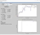
I ran my Scilab Auto Tuner
This is the output
>AutoTune("C:\Users\peter\Dropbox\Documents\Scilab\AutoTune\july2016.txt")
..............................................
FOPDT SSE=10515.449065
Kp=1.218574 Tp=0.005515 DT=0.103949
The FOPDT gains are Kc=0.004838 Ti=0.005515 Td=0.000000
............................................................................................
SOPDT SSE=3994.270493
Kp=1.050474 Tp1=0.026717 Tp2=0.191326 DT=0.099672
The SOPDT gains are Kc=0.130156 Ti=0.218043 Td=0.023443
The plant is a SOPDT
The gains are for a ISA controller. Also Rockwell does screwy things with their gains. First there is the temperature to counts, then the PID gain is unitless because the gain is counts in to counts out. Then there must be the final conversion of counts out to %control output. The controller gain above have units of %control output per degree.
The sum of square errors between the actual data and the SOPDT model is much less than the sum of square error between actual data and the FOPDT model. You need to look at my videos to see what the system identifier is doing.
It has been a pain in the rear getting the data into the right format.

Last edited:
Peter Nachtwey
Member
Why the drop in the temperature when the control output is constant? You must have a changing load.
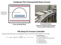
Oven/furnace has steel tunnel with electrical heating elements outside the tunnel. production parts are moving through the tunnel on a steel conveyor. control thermocouple is near the top inside of tunnel just above the moving production parts. so the elements heat the tunnel and then the tunnel radiates heat to the parts and the nearby control thermocouple. for most of time distance between parts is constant and part weight is similar.
Similar Topics
Hello, I am attempting to tune a PID loop on a process. The process involves a valve with electronic actuator that has quite a high deadband...
- Replies
- 10
- Views
- 2,163
so i have 4 25gpm wells feeding a 1000gal tank (T-1), with an additional 15gpm from a decant tank for 3hrs every 12hrs.
P1 and P2 both controlled...
- Replies
- 154
- Views
- 35,874
Hi everyone, yet another PID problem. I'm hoping I understand enough of the process I'm controlling that my request for help is reasonable. If a...
- Replies
- 113
- Views
- 27,905
A few months ago, I started to look into PID controllers and the tuning of first order processes. This has, partly thanks to you, resulted in a...
- Replies
- 162
- Views
- 62,082
I haven't had to tune a PID loop in a very long time.
It's actually a PI loop for a pulse width modulation s.v.
What was the name of that tuning...
- Replies
- 16
- Views
- 4,101


