%MX addressing in CoDeSys

Ken Roach

Lifetime Supporting Member + Moderator
Join Date
Apr 2002
Location
Seattle, WA
Posts
17,482
Hi guys, this should be a very simple question. I'm a CoDeSys novice using version 2.3 with an older Schneider LMC20 motion controller. In CoDeSys you still have the IEC style "%" memory addresses but your actual operands are Tags, many of which are mapped to memory addresses.

The addressing of controller memory based on data type is what's confusing me.

I understand that %MW means a 16-bit internal address word. It's similar to the N7:x address memory in the PLC-5/SLC-500 Allen-Bradley controllers I'm familiar with.

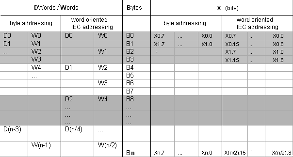
%MW47, for example, represents the 48th 16-bit Word in the internal memory addressing space of the controller. That memory space starts at Word 0.

I also have some tags that are mapped to memory addressed as %MX, which is individual Bits. It looks like the bit numbers range from 0 to 15.

So I assume (there's that word !) that an address like %MX11.5 means that it's bit 05 of Word 11.

So is %MX11.5 part of the same data word as %MW11 ?

I'm trying to figure this out because my HMI treats the CoDeSys controller like a big Modbus holding register, where %MW0 = Modbus Address 40001.
 
I think the default address numbering is in BYTES, not WORDS. So %MW11 is a word using bytes %MB11 and %MB12.

Therefore, %MX11.5 is bit 5 in byte %MB11 and %MX11.13 would refer to the same bit as %MX12.4
 
Thanks for the input ! I see that you answered my question about this sort of addressing when I dipped my toe into it a while go, so thanks for re-visiting the topic as it sinks in.

About 2/3 of the tags in this CoDeSys program have associated %MW or %MX memory addresses, which is because the LMC20 reveals its %MWxx memory space to Modbus/TCP and this system depends heavily on an HMI that brokers data between controllers.

Thanks for explaining how it would work if the address was always a byte, and the X,B,W, or D designated the datatype. I don't know if this is a standard thing or if it changes by vendor or if it's configurable.

In this system, the equivalence of %MW = Modbus Holding Register suggests that both offset values are the number of 16 bit words. In the HMI I have several Unsigned Integer type tags that are addressed to adjacent Modbus registers, e.g.:

Code:
HMI Tag                  Modbus Address  CoDeSys Tag            CoDeSys Address
Axis_1_Position_Actual   40048           A1_Position_Actual    %MW47
Axis_2_Position_Actual   40049           A2_Position_Actual    %MW48

There's that classic Modicon "1 is the first address" issue to deal with as well, of course.

Do you know of any moderately-detailed description of how the whole percent-sign addressing standard works and where it comes from ? I've read documents like "Programming Industrial Control Systems Using IEC 61131" but they start of presuming that %M and %I and %Q are all just basic vocabulary that every toddler understands.
 
Hi Ken,

The %MX address is word based as per your assumption. The mapping of the Modbus addresses depends on the manufacturer. From my experience the IO addresses are typically mapped to the lowest Modbus addresses where internal data addresses are mapped elsewhere. For example, WAGO controllers 1st internal address, %MW0, is mapped to Modbus address 0x3000 (+1) or 412287 while the I/O addresses (%QW) are mapped to 400001.

Bottom line, for the specific mapping you have to look at the user's manual.

Hope this helps. (And how do you like CoDeSys?)

Regards,

Yosi
 
Last edited:
I always worked on the assumption it was bytewise addressing. I just tried to create a tag at %IW1 and the compiler got angry. I can only align on even bytes. There must be something odd going on in the target settings of that PLC.

When I overlap byte and word tags by0 by1 make w0 and by2 by3 make w2.

The allocation of memory space is configured in the Target Settings of the Resources Tab

You might try using the ADR function to get a pointer and see the actual offset between locations.

From not very good help.

Address
The direct display of individual memory locations is done through the use of special character sequences. These sequences are a concatenation of the percent sign "%", a range prefix, a prefix for the size and one or more natural numbers separated by blank spaces.

The following range prefixes are supported:

I
Input

Q
Output

M
Memory location


The following size prefixes are supported:

X
Single bit

None
Single bit

B
Byte (8 Bits)

W
Word (16 Bits)

D
Double word (32 Bits)


Examples:

%QX7.5 and %Q7.5
Output bit 7.5

%IW215
Input word 215

%QB7
Output byte 7

%MD48
Double word in memory position 48 in the memory location.

%IW2.5.7.1
depending on the PLC Configuration


The current PLC Configuration for the program determines whether or not an address is valid.

Note: Boolean values will be allocated bytewise, if no explicit single-bit address is specified. Example: A change in the value of varbool1 AT %QW0 affects the range from QX0.0 to QX0.7.

Attention: Online Change might change the contents on addresses. Please regard this when using pointers on addresses !
 
Do you know of any moderately-detailed description of how the whole percent-sign addressing standard works and where it comes from ? I've read documents like "Programming Industrial Control Systems Using IEC 61131" but they start of presuming that %M and %I and %Q are all just basic vocabulary that every toddler understands.

Ken:

A few years ago I did something similar marrying a Pro-face HMI screen with Beckhoff BC9000 controller using Modbus/TCP. I do not remember all the details as it was a one-off project but I also had to go through the mapping of the % addresses to Modbus.

Since then, I kept a copy of a reference Excel file Beckhoff tech support (always very helpful in my experience!) had sent me - see the attached. The last tab contains a comprehensive diagram of IEC-style addressing - at least as it is implemented in Beckhoff's TwinCAT systems.
 
Hi Ken,

From some of the other CODESYS based controllers in the Schneider product line, the memory mapping usually breaks out as noted in the screen cap.


The different Modbus operations ( read coil, address , input) usually hit the various locations based on the located memory declarations.


%IX0.0 -> Modbus Input address of 10001
%QX0.0 ->Modbus Coil address of 00001
%MW0 ->Modbus holding address of 40001.


I'm not familiar with the LMC20 but the breakout should be similar.

From a implementation perspective, I tend to use a specific data type across an address range and package information into it contiguously.. This helps define a standard space allocation for planning purposes. Example: I may declare all my MW's from location 1000-1500 ( MW1000-MW1500) and then I would declare MD's in a different address range- maybe 1600 - 2000.( MD1600-MD2000)

The contiguous declarations also help with read/write operations in Modbus or Modbus TCP where a single read/write can pick up a number of addresses.

Technically, I believe MD's and MW's could have the same numerical address declaration but this might lead to confusion and errors in reading/writing. With space being less of an issue these days, spacing it out is probably a good idea.

_________________________________________
http://www.drivesandsystems.com

LocatedMemory.jpg
 
To add to LadderLogic's contribution:
Here is a (may be partial) Modbus Register Map for Turck BL67.
It came from a Turck Product Engineer for Network and Interfaces.
It may align with the BL20 mapping.
I don't know if it aligns with Schneider LMC20.
 
Here is Beckhoff's explanation of IEC addressing:
http://infosys.beckhoff.com/english.../1033/tc3_plc_intro/9007199391239307.html&id=

It mentions several times that IEC addressing is word based. They also have a chart showing correlations between word and bit addressing. To answer one of your original questions, it looks like %MX0.[0..15] and %MW0 are accessing the same memory space.

137949195__Web.png
 
So the answer is sometimes bytes sometimes words depending on the target because the PLC I have in front of me does byte addressing of %MW.

Thanks CoDeSys for gotcha number 9734.
 
schneider works IEC style so you are correct with 16 bit words.
however %MW0 has %MB0 and %MB1.
so you will need some calcs to get it reaqd from 40000
 

Similar Topics

I am very new to Modbus and the industry, so forgive me if I am missing something obvious. I have known Modbus register addresses coming from a...
Replies
7
Views
201
I have a system using Rx3I CRU320 redundant CPU with Proficy Machine Edition Software. In the hardware configuration of each CPU module, under...
Replies
14
Views
372
See the screenshot of EIP tag list. We are trying to read in a digital input that is hard-wired. It is shown here as I31.1. I believe we cannot...
Replies
7
Views
269
Hello all. I have a Simatic SM374 (374-sxh01-0aa0) sim module. I am using TIA portal v.18. I can't find this module in my list of hardware devices...
Replies
12
Views
741
Hello, I have a device with 68 words input. But one block on the Devicenet Scanner is only 61 words. I am trying to map this device to 2...
Replies
3
Views
520
Back
Top Bottom