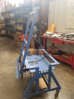
Jig for building control panels

Snap25

Lifetime Supporting Member
Join Date
Dec 2014
Location
Michigan
Posts
237
I'm looking for some ideas toget inspired! I've been building a lot of control panels lately and I feel like in doing everything the hard way! I typically just set the sub panel on a bench and measure from point to point to get my wire ways and din rails in place (never square enough to my standards..) I usually stand the sub panel up to wire it..


I was thinking of building an adjustable frame out of square tubing and build a swivel mount to adjust my angle then lock it in place..

What is everyone's panel building routine or set up look like?
Small panels, like you described.
Larger or duplicate panels, CAD, print, tape to panel, ding the hole pattern, drill, tap, mount.

I have known some to give the drawing file and panel to the machine shop - byt I usually don't have 3-5 days to wait.
 
I'm looking for some ideas toget inspired! I've been building a lot of control panels lately and I feel like in doing everything the hard way! I typically just set the sub panel on a bench and measure from point to point to get my wire ways and din rails in place (never square enough to my standards..) I usually stand the sub panel up to wire it..


I was thinking of building an adjustable frame out of square tubing and build a swivel mount to adjust my angle then lock it in place..

What is everyone's panel building routine or set up look like?
Small panels, like you described.
Larger or duplicate panels, CAD, print, tape to panel, ding the hole pattern, drill, tap, mount.

I have known some to give the drawing file and panel to the machine shop - but I usually don't have 3-5 days to wait.
 
I built 2 adjustable tilt tables when I was working for a machinery builder years back - 1 for full size floor cabinets and 1 for assorted smaller cabinets. I could mount the sub-panel or the cabinet. It would lay flat or tilt up to 90° and lock at any angle. Also the tables were designed on scissor lift bases so the height was adjustable.

For laying out I bought a roll of refrigerator magnet material, cut out the shapes of common items and put small holes for a center punch where the mounting screws needed to be. For fuse blocks, breakers, contactors and other things there would be a few of I made a bunch of each magnet. I could set the magnets in a row, make sure they were all straight and level, and had good spacing between them - then mark the drill holes.


EDIT: And they can be written on with a Sharpie for what exact component they were for.
 
Last edited:
Drilling holes accurately in large panels and doors is a real PAIN! I have thought several times about building a fixture from a CNC router table and a small drill press to locate the holes but never got around to doing anything.
 
Many enclosure distributors offer CNC services affordably. If I don't have time for that or I just want to do it myself I also do the CAD, print, tape, etc. I'll also use local machine shops to make drilling jigs for "mass" production.
 
Drilling holes accurately in large panels and doors is a real PAIN!

I once built a cabinet that had on the door 13 each Start PB, Stop PB and indicator light. The customer bought all 30.5mm oiltite switches and lights.

I had to lay out by hand, without laying the panel down, 39 holes in 3 rows, 13 columns, straight, square & level to each other, with the keys in the oiltite holes all pointing straight up.

Pilot hole, 1/2" conduit punch for the 30.5mm draw stud, then with a manual oiltite punch, no hydraulic Quick-Draw like now.

2 day job that now would take me 1 hour.
 
This is a typical panel size for me. They may get a little bigger but they never really exceed 6'x6'.

I do like the magnet idea, I'm going to give that a try!

It's just a pain in the *** man handling the sub panel on a bench and then on the floor to et it up right to start wiring. Then man handling it into the enclosure (don't even have a routine for hat, play it by ear each time)

There has to be an easier way to move this thing around and place it in the enclosure.

image.jpg
 
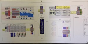
Somewhere deep in the "Control Panels Pictures" thread there's a post by Archie describing how he prints the layout onto signwriters vinyl and attaches it directly to the panel. Thought it was a brilliant idea, but have never tried it myself, the attached photo is from the thread.
attachment.php
 
Can't help you with the handling (unless you've got a crane) but I made some simple wooden blocks out of 2x4 pine so that when I drop the sub-panel into the enclosure it comes out exactly the right height to go on to the studs. I just set the blocks in the bottom of the panel, drop the sub panel in, then remove them.
 
Can't help you with the handling (unless you've got a crane) but I made some simple wooden blocks out of 2x4 pine so that when I drop the sub-panel into the enclosure it comes out exactly the right height to go on to the studs. I just set the blocks in the bottom of the panel, drop the sub panel in, then remove them.

Years ago, I worked for an automotive supplier/oem...
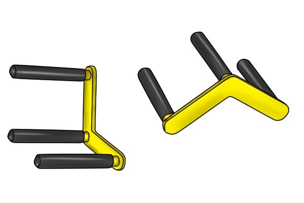
To get the not-so-large panels across the shop, we used something like this (don't remember the brand, but "http://www.wonkeedonkeetools.co.uk/door-and-board-carriers/what-is-a-static-grip-door-and-board-carrier" is similar
26DBC-11-3.jpg

and for the larger panels, we used a fork-truck with cleats (looked like a very small kindorf strut channel) welded to the forks for assist.
 
Only on rare occasion I build my own panels. It is usually done by someone else at the shop and sometimes even an outside contractor brought in. In order to guaranteed the panel is easily built exactly the way I intend, I developed the technique shown in the picture ggc posted above from an older post. With this method, it guarantees the components will be mounted exactly where I want them. Even most of the hole locations are cross haired, so the panels are built without using a tape measure.

The real advantage comes after it is completed. All of the components are labeled as part of the drawing that is applied directly to the panel making it incredibly easy to troubleshoot once installed in the field. Attached is a picture of another panel showing it right after it came from the print shop and before any components are mounted.

IMG_1963Small.jpg
 

Similar Topics

Hi guys, once again my memory betrays me, I'm almost certain I've seen a jig to hold small parts in place that somehow looked like a pinart toy...
Replies
0
Views
283
Hi guys, We've come across a project to construct a test jig for pulling test on an object. There is a hydraulic pump to do the pulling (length)...
Replies
6
Views
6,049
Anyone here can give me a copy of programming manual using cjig-cpu43h series.. (OMRON) thanks in advance...
Replies
11
Views
6,061
Hello everyone, I am a student and would like to take the next step and learn FactoryTalk (Batch preferably) and how to create HMIs etc. Would...
Replies
4
Views
490
Hi all Trend seemed to have carved a niche in building controls. The controllers seem expensive and inflexible, in the words of a Trend user. Do...
Replies
1
Views
489
Back
Top Bottom