whoops, they got npn when they need pnp

ganutenator

Lifetime Supporting Member
Join Date
May 2002
Location
kansas
Posts
1,440
they have npn prox sensors but we need pnp (sourcing pos 24vdc logic to a sinking card)

I solved the problem using relays.

Someone smarter than me told me that I could have used pull down resistors.

thoughts?
 
I am not a fan of using discrete components (like resistors and diodes wired to terminal blocks) in industrial enclosures. I have used a product many years ago I believe it was made by Turck that was an inline converter made to plug into a 4 pin M12 connector.

This may be the same one I have used:
http://www.alliedelec.com/turck-spn1-ap6-arn6x/70259638/

Another time I had to do exactly what you did...for 20 sensors. We had enough relays and panel space available and it was urgent. I strongly disliked having a bank of relays for solid state photocells, but it got the machine working while we waited for another thousand dollars worth of sensors to arrive.
 
but $67 bucks though.

I bet there are cheaper ways to go. How much is your time and downtime worth?

You can plug in a dozen of those things a lot faster than I can wire up a dozen relays...

And it is solid state so switching frequency and longevity are factors to consider not to mention ease of maintenance compared with using resistors in a panel.
 
they have npn prox sensors but we need pnp (sourcing pos 24vdc logic to a sinking card)

I solved the problem using relays.

Someone smarter than me told me that I could have used pull down resistors.

thoughts?

If these are going into a PLC, why not get a different input module?
 
they have npn prox sensors but we need pnp (sourcing pos 24vdc logic to a sinking card)

Someone smarter than me told me that I could have used pull down resistors.
To get technical, in this scenario it would be a pull up resistor. Realize too that technique also reverses the logic of the switch, N.O. become like a N.C. and vise versa.

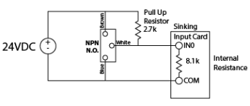
You must also consider whether the voltage drop is acceptable. Consider the circuit in the diagram shown in the attached picture. For the purpose of explaining, the internal resistance is unusually low and made a nice value for calculations.

When the prox switch is not activated, all current will flow through the pull up resistor and through the internal resistance of the input card. This forms a voltage divider. If you calculate this out, you will get 18 volts on the input of the card. Will the card interpret 18 volts as on or off? It depends on the card, but the goal would be to be above the threshold for making the input as high/active. Also note the switch is off, but the input will be active, therefore reversing you logic.

If 18 volts is too low, the voltage making it to input card can be increased by lowering the value of the pull up resistor. But you must also consider the power dissipation of the resistor. When the NPN prox switch is active, it will pull the one side of the resistor to the dc common or 0v. Using your basic electrical calculations with 24V across a 2.7k resistor, you will come up with about 0.21 watts of power, therefore needing a 1/4 watt resistor. If your voltage drop is not acceptable and you have to lower the resistance, then you must consider how much higher do you need to go with the resistor power rating.

PullUp.png
 
To get technical, in this scenario it would be a pull up resistor. Realize too that technique also reverses the logic of the switch, N.O. become like a N.C. and vise versa.

You must also consider whether the voltage drop is acceptable. Consider the circuit in the diagram shown in the attached picture. For the purpose of explaining, the internal resistance is unusually low and made a nice value for calculations.

When the prox switch is not activated, all current will flow through the pull up resistor and through the internal resistance of the input card. This forms a voltage divider. If you calculate this out, you will get 18 volts on the input of the card. Will the card interpret 18 volts as on or off? It depends on the card, but the goal would be to be above the threshold for making the input as high/active. Also note the switch is off, but the input will be active, therefore reversing you logic.

If 18 volts is too low, the voltage making it to input card can be increased by lowering the value of the pull up resistor. But you must also consider the power dissipation of the resistor. When the NPN prox switch is active, it will pull the one side of the resistor to the dc common or 0v. Using your basic electrical calculations with 24V across a 2.7k resistor, you will come up with about 0.21 watts of power, therefore needing a 1/4 watt resistor. If your voltage drop is not acceptable and you have to lower the resistance, then you must consider how much higher do you need to go with the resistor power rating.


awesomeness
 
Not just Automation Direct. A lot of PLCs these days have sink/source input cards. Take a look at the sample wiring diagrams, you may be able to just switch the input common from 0VDC to 24VDC to switch the input type.
 
well with a simple resistor and a transistor it will work correctly, and you can turn the logic again to get the signals NO again.
 

Similar Topics

Hi All, Someone at work has put a PLC system on my desk, that's just been taken off an idle production line. He said "It's an S7 PLC. We don't...
Replies
8
Views
117
Hello everyone, its been 8 years since I frequented this forum. I had a lifetime membership with my old profile, but could not remember my...
Replies
17
Views
948
I'm trying to manually convert a Beijer E200 HMI project onto to a new Mitsubishi GOT gs2107-wtbd. The PLC is a very old A-series AS1CPU and is...
Replies
1
Views
381
Is there an output or something that is similar to a screen saver, but you can use in the plc to know when the user is actively using it...
Replies
1
Views
502
Back
Top Bottom