Out of my depth - Feed forward, Cascade?

TheWaterboy

Lifetime Supporting Member + Moderator
Join Date
May 2006
Location
-27.9679796,153.419016
Posts
1,924
What technique would I employ when I have a tank that I am pumping out of at the same time water is flowing into it and I want to keep the flow as consistent as possible while making sure the tanks level doesn't get out of hand?

Currently I focus on the tanks level and a PID controls that quite well. A side effect due to the inconsistent inflow is that the VFD driven pump changes speed to maintain the level and the effluent flow obviously varies along with it. Sometimes quite a bit.

I would like to change this configuration so that the effluent flow remains much more consistent and the tank acts as the influent accumulator and changes to the level are permitted within a certain boundary with only a slight increase/decrease being felt as effluent flow.

I of course will need to sacrifice consistent effluent flow should the Tank level change dramatically or get to a dangerous level, but otherwise a couple feet of variance is OK if it would give me more consistent effluent flow.

What technique would I use to create this 2 input type of control? I have never created a cascade of PID's or "Feed Forward" (but have heard the words before :) ) so I would need to do my homework to figure out how to construct one, should one of those options, or some other, be the proper technique to use in this instance

I would greatly appreciate opinions on the correct control strategy I should follow.
 
Search the forum. There was a discussion of a very similar system less than a month ago. You will learn a lot just by reading that.

You need to be very specific, usually by creating a schematic or P&I diagram, about what you are measuring and what you are controlling. Only then can people have an intelligent discussion about your system.
 
In did it several years ago, you must be sure that input flow (input pump GPMs )is always bigger that output flow (output pump gpm ).
This way you can restrict input flow while maintaining output flow steady and level steady. I use two PIDEs one to maintain output flow together with a flowmeter and a VFD ,and the other PIDE is used to control level with a valve and a level transmitter.
 
I can't control influent flow to the tank - surges in flow are normal as flow switching takes places earlier in the process, but overall the intake of the process should match the outflow. If I could count on the influent and effluent meters being dead accurate with each other I could probably use that, but experience tell me not to trust that to work out well. :)
 
Read my posts in the other thread about making the whole system a big low pass filter that smooths the flow with no attempt to control to a level perfectly.

I did and I am trying to understand your paper. It sounds like exactly what I am trying to do, but . . . . I'm not an engineer and I am struggling to wrap my head around it.
If this was in PLC code I could probably grasp it, but as pure math I suffer.
 
Don't you have access to a senior engineer or head engineer? If not then ignore all the math. The fancy math just shows how my idea would work.

Do you know how to make a controller with a proportional band? The SCP instuction is good for this. The input limits are the low and high fluid levels. The output limits are 0% and 100% pump speed. The input is the tank level and the output is the pump speed.

Next do you know how to make a low pass filter?
See other thread here about low pass filters.

What all the math says is filter the tank level using a low pass filter. Basically the low pass filter is filtering your flow. Use the filtered tank level as the input to the SCP block. Simple, the only real trick is choosing the filter constant. If you filter too much the actual tank level may over flow.
 
Peter
No, I am the top of the food chain in that regard. (and isn't that a sad state of affairs...) I have access to a lot of civil engineers, but none for control systems.

Normally its not a problem but I am always trying to improve the system while keeping it simple enough for the next guy and so I occasionally require more brain cells that I have left. This is one of those times.
 
HMMMM

Much -a-do

Omega stocks some pretty good ones, but you'll need a flow meter with a 4-20 output that can be inverted.

Put the flow meter on your tank entrance (input). Invert your signal, 20 ma = 0, 4 ma = 100, you can choose to filter this through a plc or connect it directly to the VFD. Eventually they will meet in the middle. For an over run, a simple level switch to override flow meter control and put 100% on the VFD. When the switch is released, return to the flow meter control.

Control the integral by increasing/decreasing the ramp up/down time on the VFD depending on how far away the entrance is from the pump.

Have fun
 
Last edited:
My apologies, I was a little vague.

You wanted to maintain the flow into and out of the tank. Correct?

Tank level was assumed, and an increase in flow would have tripped the level switch to increase the VFD to 100% output. assuming the level would reduce below the switch, then the flow ( level ) would have been maintained based on flow.

Unless your talking about the BIG tanks on the sewage treatment farms, in which case I have no idea what you need.

We ran a water tank ( reversed ) flow on the output. Used the flow meter ( inverted ) to maintain level based on the amount of water that left the tank. A low level switch turned everything off. A high level switch would over ramp the VFD to 110%. Neither switch and the VFD was driven off the exiting flow.

If the 110% was maintained for more then ten minutes, we had a high water alarm.
 
Have look at this excel sheet from Tom Jenkins, it is a simple filtering formula with some data and a chart for a visual. Study this and understand what is happening. He has a few columns with different filtering constants to allow you to compare the results of different constants. This is the first part of the solution Peter is referring too.

http://www.plctalk.net/qanda/showpost.php?p=612862&postcount=4

The second part of the solution is to control the pump speed proportional to the filtered tank level which is pretty straight forward per Peter's explanation. Just analog scaling.

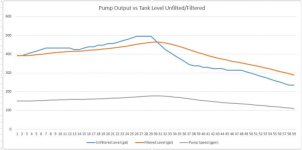
Attached is a quick chart to visualize the solution. The blue is an unfiltered level in a tank. The orange is a filtered level (Tom's formula), the grey is the actual pump output. In this example, my tank capacity is 785 gallons, the pump capacity is 300 gal/min. I threw arbitrary tank levels in to simulate unfiltered tank levels and subsequent pump control speeds.

You can see the pump output speed is filtered to match the filtered tank level, the control is proportional to the tank level. As Peter mentioned, the trick or the "tuning" parameter here is the constant in the filtering formula. Too little and you won't "smooth" response on the pump, too much and you risk overfilling or running the pump dry due to the pump not responding fast enough.

The first chart I attached is probably what you need to shoot for. The second chart would be an example of too much filtering, you can see how it might overfill or run dry.

chart.jpg Chart2.jpg
 
Its like averaging... And yet its not.

Remember my goal is to keep the output as constant as is reasonable. Not exact, that's impossible, but my current method allows effluent swings of 2 MGD all day long. If I could keep these swings to less than .2 mgd using the large tank (250K Gallons) as the "dampener" that would be OK.
 

Similar Topics

Good morning guys, I'm searching to find a product that can inspect the width and depth of a keyway on the end of shaft. Width is 1/4" ±.001...
Replies
0
Views
286
Hi My Name is Jason Woods and I work in HR at Honeywell. I have multiple positions that we are seeking knowledgeable individuals that have...
Replies
0
Views
2,367
I've gotten a lot of help from this site and you guys but I wouldn't want to waste any body's time. Should wait and find more technical, in depth...
Replies
3
Views
1,761
We have a new line being added in one of our facilities. In our switch gear, we have a spare 400A breaker which we were going to use to feed power...
Replies
4
Views
2,134
Hello all, as you probably are all aware I have been trying to interface an A&D GX4002A balance to a 1769-L24ER-QBFC1B controller by the use of a...
Replies
7
Views
1,476
Back
Top Bottom