1771-IF8 with ControlLogix

thebuj

Lifetime Supporting Member
Join Date
Aug 2014
Location
New Brunswick
Posts
90
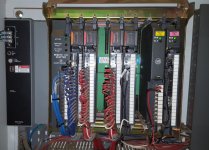
Hey guys, I'm going to be replacing at PLC5 cpu with a 1771-ASB and control the racks using an L71 cpu. I got the discrete IO all converted and my control logix program is pretty much done. I'm having problems understanding the analog cards though.

I have one analog out card and one in. The analog out (5/3/0) controls an air pressure valve and the analog in (5/3/1) reads an ultrasonic sensor. The data from the sensor is used to calculate the air pressure to output on the analog card.

I've hit a wall with the analog input module. It has both a read and an write transfer block and I don't have enough experience with configuring PLC5's and I don't understand whats going on.

In my opinion the comments on rung 24 should be really for rung 23 and the comments for rung 25 should be for rung 24.

That leaves me with rung 25 which I don't understand what and why they are writing to an input module.

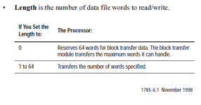
As you can see N24:101 is nowhere else in the program and N24:131 is also nowhere else in the program. Since both lengths are 0, am I right to assume that only the data file indicated in the control block get written/read?

Anyone know whats going on?

2016-09-19 18_25_07-RSLogix 5000 [Running] - Oracle VM VirtualBox _ 1.jpg

2016-09-19 18_25_36-RSLogix 5000 [Running] - Oracle VM VirtualBox _ 1.png

halfrack2.jpg
 
Not sure why the lengths should be zero in there....

for 1771 analogs out, you write out values like channel config and scaling, then read back the channel values.

For analog in, you would write out the scaling parameters, as the channel config is done by jumpers in the card itself. You would then read back the channel values using the BTR...

If you click on "setup screen" in the BTR or BTW, does it give you anything? It is documentation, but it does help (sometimes) to understand what is going on.

if they are not setup, then you can create the screens and fill in the BTR and BTW data to give you a pop-up when you click on setup screen.
 
From what I gathered, I may not be getting any data from the ultrasonic sensor, we have a compensation selector that adds pressure if the calculated value isn't enough. So it would be possible and we would still be able to run the machine.

I get an error message that the module isn't configured in the IO configuration when I click setup.
 
if you're allowed to post your ENTIRE project file (RSP extension) we can offer you more detailed help ...

here's just one tip:

Since both lengths are 0, am I right to assume that only the data file indicated in the control block get written/read?

no, that's incorrect ... see below ...
.

btw_length.PNG
 
I get an error message that the module isn't configured in the IO configuration when I click setup.

this link might be helpful ... (suggestion: try this on a spare COPY of your RSP file) ... based on what you've posted so far, I'm GUESSING that your settings will be for an 8 slot chassis - and for 2-slot addressing ...

http://www.plctalk.net/qanda/showthread.php?p=137747&postcount=7

also ... the title of your thread mentions a 1771-IF8 ... are you sure that's not a 1771-IFE module instead? ... and if so, is it a series /A or /B ... or possibly a series /C ... it makes a difference when setting these up ...

if you could post your ENTIRE project file (RSP extension) that would eliminate a LOT of the guesswork involved with this project ...
 
Last edited:
Thanks, JohnCalderwood, with what you gave me I realized I was missing a lot so I went to the manual and of course it is all explained.

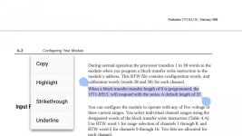
Mr. Beaufort, if I write 64 words to N24:101, wouldn't that overwrite N24:131? But the picture you posted is a reference for 1781 cards, is the value less than 64 on 1771 cards? I looked in the 1771-IFE manual and I can't find it.

2016-09-20 07_17_07-RSLogix 5000 [Running] - Oracle VM VirtualBox _ 1.png

I have multiple racks. My modules are in 5/3/0 and 5/3/1. So I'm having a hard time creating the IO configuration for the 1771-IFE , yeah you are right, its an IFE and not a IF8. I'm not sure on the revision, I will need to wait for the machine to stop tonight.

I'm not too worried about getting it setup in IO Configuration. Its going to be running on control logix pretty soon.

But with the information you gave me, I should be able to replicate it in control logix and get it to work.

Thanks again guys.
 
Mr. Beaufort, if I write 64 words to N24:101, wouldn't that overwrite N24:131?

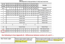
not necessarily ... notice the part that says: "the block transfer module transfers the maximum words it can handle." ... basically the module only transfers as many words as it "needs" (that's either 20 or 22 in most cases) ...

the figure shown below might help ... here's a link to that manual ...

http://literature.rockwellautomation.com/idc/groups/literature/documents/um/1771-um663_-en-p.pdf

and moving right along ...

But the picture you posted is a reference for 1781 cards

actually the picture that I posted was from page 15-5 of the Instruction Set Reference Manual for the PLC-5 processor ... that's the manual that fully covers the Block Transfer Instructions (BTW and BTR) ... here's a link in case you need it ... see Chapter 15 ...


http://literature.rockwellautomation.com/idc/groups/literature/documents/rm/1785-rm001_-en-p.pdf

good luck with your project – it sounds like you've got it figured out now ...
.

BTR_table.jpg
 
Last edited:
I checked the model and revision of the cards and 5/3/0 is an 1771-OFE2 B and 5/3/1 is an 1771-IFE SER. A FW. F.

I created the IO config for the cards but it brings me more questions...

2016-09-20 17_16_05-RSLogix 5000 [Running] - Oracle VM VirtualBox _ 1.jpg

2016-09-20 17_14_45-RSLogix 5000 [Running] - Oracle VM VirtualBox _ 1.png

The data file is N24:101, but in the card's page, it starts N25:105, yet I seem to be getting input data on N24:104 when I look at the data table.

Did I even configure it correctly?
 
It's hard to help you if you keep ignoring the help posted....If you look at Ron's post right above yours, you'll see that the first 4 words are occupied by Diagnostic and Status data on the BTR. N25:104 would not be "Data" from a channel but the polarity of each channel.
 
Look, I read the manual several times before posting and did a few google searches too. I looked at the charts Mr. Beaufort posted and it still didn't make sense to me. I didn't think there would be config files in the read since we already write to the input module and that already confused me.

I came into the trade on control logix v16. Block transfer reads and writes to a card, addressings and getting configs in words is something else for me. What seems to be childs play for some, might be gibberish for some.

So I'm obviously not ignoring information deliberately just for the sake of conversation, attention or getting my post count up, but simply not understanding how this all works.

Now I do understand,

Thanks
 
Yes thanks a lot, like I suspected, I'm not getting any data from the ultrasonic sensor, but I can run the machine without it so I will not troubleshoot it. I am switching the rack to control logix soon so I will make it work then.

You guys have been great help

Thanks again
 

Similar Topics

Urgent!! Hi all I am a newbie here. Currently I am migrating from plc-5 to controlLogix. When 1771-IFE change to 1756-IF16, I am getting a...
Replies
4
Views
2,379
Preface: Kinda long, so I made section titles Intro: I just want to see if anyone here has seen anything similar. A PLC5-40 series C enhanced...
Replies
3
Views
365
Existing environment shown in attached photo (Existing.jpeg) Proposed Environment shown in attached photo (New.jpeg) I am migrating a PLC5 system...
Replies
0
Views
590
I have a 1756-L81e v32 using a DHRIO v7.001 in RIO scanner Driving (7) 1771 ASB Modules @ 115k baud. The Racks RPI are set at 48msecs. This system...
Replies
2
Views
897
Hello, I am setting up for practice and I am having trouble seeing the 1771 Scanner in RsLinx as well as Rsnetworx My setup: slot 0 : PLC-5/40E...
Replies
3
Views
976
Back
Top Bottom