PLC5/40 Remote IO addressing

Dsager01

Member
Join Date
Nov 2007
Location
Tennessee
Posts
7
I have a PLC 5/40 that lost its program that ive recreated via a printed copy. Now im working on all the channel configuration. On channel 1B I was able to autoconfig and it found all the devices (1395 DC drives) Now im working on channel2A and can not get it to autoconfig.....

Channel 2A is hooked only to a 1771-ASB in a 16 slot rack. There are 8 1771-IAD cards and 1771-OAD cards. The dip switches are set to

Backplane 1-off 2-on 3-off 4-off 5-on 6-off 7-off 8-off
SW1 1-on 2-on 3-on 4-on 5-on 6-off 7-on 8-on
SW2 1-off 2-on 3-off 4-off 5-off 6-off

Should i just manual config the channel configuration and give up on autoconfig? if so i have no idea what to manually enter. are the first 8 slots rack 1 and last 8 rack 2?

Anyhelp would be greatly appreciated.

Thanks,
Doug
 
Based on your switch settings, the chassis is configured for 1-slot addressing. And I am assuming those are the switch settings for the REMOTE chassis, not the Local chassis.

The ASB module is set for Rack #1, Group 0. It is set for 230K baud. It is also set to scan all but the last 4-slots. Perhaps that 230K is why you could not auto-config. Make sure the channel is also set to that same speed.

Since you have a 16-slot chassis you would manually make two entries.

Rack 01, Group 0 Full Rack for the size
Rack 02, Group 0 1/2-rack for the size

OG
 
You are correct it is a remote rack. I will give those settings a try tomorrow. I made sure I had the channel set to 230K but it would give me an error for no IO status file ( but worked fine for channel 1B). I have a question about it being set to scan all but the last 4 slots. What does that mean? I have cards in those slots? Do i have to do something diffrent? Also how do you configure the local rack?

Sorry for all the questions all ive ever done with PLC5 is maintain them.
 
Nothing to configure on the local chassis. Just plug in and go. The only setting really to know is the backplane switches that set the addressing mode as 1-slot or some other method.

The setting to not scan the last four slots would allow you to put modules like power supplies in those last slots. Normally when you put a power supply in the chassis, the I/O points assigned to those slots are lost (inaccessible). So putting say two redundant power supplies in the chassis would cost you all the I/O assigned to the two slots. With the setting to not scan the last four slots, no I/O gets assigned to those slots so there is no loss of usable I/O.

Switch 2 (the one with six dip switches) is where that setting is changed. Switch #4 On/Closed is all but last 4 slots. Switch #4 Open is scan all slots.

That changes the I/O configuration for Rack 02 to a Full Rack.

The I/O Status file is required for auto-config. Just enter in the number of a new integer file that it can create. For example, if you type in "30" it will create N30. Not sure why it would have worked for channel 1B without it.

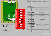
Below are the typical settings for the chassis backplane dip switches with a PLC-5 installed.

OG

DipSwitches.JPG
 
Last edited:

Similar Topics

Hello. Could anybody with PLC5 networks experience give me some idea what could be wrong with our network? We have Controller 5/25 with remote I/O...
Replies
19
Views
5,716
Hi, i need help, i have a plc 5/80c 1.5 and the i/o config is: Local chassis (4 slots) onnly the processor and also 4 chassis each (16 slots)...
Replies
1
Views
1,470
Hello All I have a customer with a PLC5 that needs to add an additional Remote IO drop. The problem is there is no practical way to install a blue...
Replies
2
Views
1,794
I have 2 slc5/05 plc 's connected over ethernet. I am able to have one Plc read any word from the second successfully for example if I have Target...
Replies
8
Views
1,935
My goal is to get an analog signal from a SLC-500 remote rack back to a PLC-5 main rack. Is this possible? If so, I may need some help. I've set...
Replies
4
Views
1,760
Back
Top Bottom