ML1400 Messaging

Nhrafan26

Member
Join Date
Nov 2008
Location
Slatington, PA
Posts
53
Been a long time since my last post and I was just learning even what a PLC is. Since then I have been fortunate to work with some great guys and learn from them and been in a few positions that have allowed me to troubleshoot and modify logic as needed.
]Now I am in a position where I am writing my own programs and making everything work together.
Where I am getting stuck is the messaging. We use some not so normal things here to get our information across which is interesting.
Right now I am trying to set up a heartbeat message as well as the transfer of information to a server. I am using a micrologix 1400 seriesB and going over ethernet. I have the IP set up for this and the server is able to see it. I have the server IP as well but I am not sure how to set up the message instruction along with the ER EN DN etc bits.
I am looking at the message like a timer right now and I think that's wrong. What I mean is looking at it as the rung goes true, the EN bit sets, the message completes, the DN bit sets or ER if there is an error like a timeout. Then you reset the rung and start over.
Can someone explain it a little better so I can get a better understanding of it? I have read the help files and read through most in the book but something with an example would really help.
 
You are essentially correct. MSG is edge triggered and execute once when the rung goes true. Some people would use the .DN bit and run the MSG as fast as possible that that put a lot of strain on the bandwidth and processor. Better to trigger it on a timer in conjunction with the .DN and .ER bit.

See here:

http://www.plctalk.net/qanda/showthread.php?t=6527

Ok, read through that and it helped a little bit. I was not able to open the zip file associated with the one post but don't think it matters much.
I have a program here written by someone else and was trying to decipher what they were doing, now I believe it was using one of the methods or a combination of some listed in the link you posted.
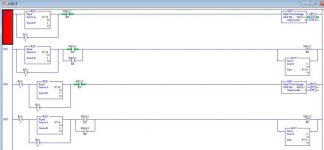
I'm going to try and post up the rungs and see what you think.

Messagingexmp.jpg
 
I think I'll need that reading glasses soon.. yikes.

If I'm seeing it correctly...

- N7:14 is used as the index to sequence the two MSG instruction
- I'm quite sure the unlatch of the enable bit is unnecessary. Once the condition preceeding MSG goes false the ENable bit should be off.
- I'm guessing B3:0/0 and B3:0/2 are used for testing.

I would suggest a timer delay in the sequence. That is, once a MSG is DoNe, delay a bit before increment the index.
 
Ok, so the mov at the end is used for indexing?
How would the message files know which is which?
I looked at where used and this is the only place this address is in use.
There are several files like this one after another. The first is 3, second is 5, 3rd is 7 and 4th is 8.
Now I see the EQU in the beginning of each does correspond to the number in the Mov file. So what that's doing is setting an order for the messages to be sent. Got it. That makes sense now...EXCEPT I do not see any MOV or any enable bit for #2 to start the others and when online I did not see those active. I'm thinking whoever did not clean up the program very well before loading it in.
Can you see any issues with removing the unlatch output?

Messagingexmp.jpg
 
Another question is for scanning...
They have 3 different ladders set up with different addresses for indexing.
My question is could you not use subroutines to schedule which got scanned and when?
Does it matter what ladder something is in in relation to scanning?
What is the scan order of a plc with 4 ladders and 2 subroutines set up? That would be my question...?
 
Yes, the MOV is used for indexing. All it does is increment the index.

I don't see any issue with removing the Unlatch, but it's not doing any harm either. You can always remove it and watch the result.

Your screen shot is too fuzzy to me to read the numbers well. But it does looks like a typo on the MOV statement to move 3 into the index, it probably should be a 2.

On a micrologix, you have a main ladder logic to call on subroutines. The scan of the subroutine depends on the order of JSR.
 
Ok the thing with this setup is that it's kind of a mess...
They didn't believe in plcs and didn't really want to use them. The only reasoning they are here now is simply messaging.
Then i came along, and am currently fixing the system and getting us set up for the future. So while I'm trying to figure out their quick setup in also trying to integrate my new system into theirs.
I think I'm going to start a new thread for that though.
Right now I'm just trying to get a good grip on the messaging part since that's the gap between my plc and the server right now.
 
transfer of information to a server

Can you tell the forum more about this "server"?

Normally a server (PC,SCADA,HMI) will poll the PLC for the data it wants. Using a message (to read or write the data) instruction is unusual.
 
That is what i thought. I will have to talk to our database programmer more, i have tried asking what he needs besides the files where i have info stored but he just mentioned about the messaging, particularly the "watchdog". That is all I'm going to look at putting in right now.
The server is based on modbus and is a virtual server exactly.
 
I have attempted to set up a message the same way as a sample program from here and all I get is the ER bit set, nothing else happens.
How do I find out WHAT error is being generated or what is wrong?
Is there anything that can point me in the right direction at least?
I don't even know where to look at this point.

Expand the Setup Screen of the MSG instruction. (Double Click on the "Setup Screen" spot on the bottom of the instruction.

It should give you information about what the error is in that page that pops up.

There are many things that can cause the MSG instruction to error. So you will have to start with what the error is, and verifying the setup of your instruction vs the setup of your physical network.
 
I am getting a local communication channel is shut down message.
But yet when they tried before they could ping the plc from the virtual server and can see the connection.
I have the correct IP in but modbus is not something I've programmed before either.
 
ML1400 Modbus communications

Still not communicating properly or successfully.
I am getting a "Reply not received before user-specified timeout" message.
It looks like it tries for 33 seconds and then faults. (ER)
I have other PLC's messaging in the same plant that I have looked at and see nothing different in their code compared to mine for messaging or comm setup.
Anything I need to be looking at or any more information you need to help on this one?
Is there a modbus person on this forum?
 

Similar Topics

Good morning all. Does anyone know where a sample program is located to message data to and from a Banner VE Series camera from a ML 1400? I am...
Replies
32
Views
12,142
Hello, I am trying to send descrete I/O data between 2 Micrologix 1400 PLC's using messaging instructions. Can anyone tell me if I have to use an...
Replies
3
Views
2,343
Hi All, I was wondering if it is possible to send ASCII commands via Ethernet messaging with a ML1400? I have to send instructions to and from a...
Replies
5
Views
3,659
I am attempting to map registers from N10 in Micrologix 1400, to Modbus addresses at a customer’s PLC, over an Ethernet connection. All the...
Replies
8
Views
3,939
Hi all, Still pretty new to PLC's in general and brand spanking new to messaging. Trying to read from one ML1400 to another over ethernet. For...
Replies
2
Views
2,672
Back
Top Bottom