First Time Using 4-20mA/1734-IE4C Module

jfd7851

Member
Join Date
Mar 2016
Location
New Orleans
Posts
19
Hi everyone,
As stated in the title, this is my first time configuring a 4-20mA device and I am using Rockwell's 1734-IE4C module as part of the Point I/O module. The sensor I am connecting has three wire leads. One is red which I am assuming is +, One is black which I am assuming is - and one is green which I'm assuming is ground.

Based off the amount of wires and the picture from the IE4C manual, it seems like I would connect the red + into one of the input channels, black into the common, and the green into the Chassis Ground terminal?

If anyone has any experience wiring 4-20mA and could offer some words of wisdom, I would greatly appreciate it. Thank you.
 
Thanks. Doesn't the Point IO supply the 24VDC? Right now, I've got the red wire into the Channel 0 "IN" terminal, the black signal wire into the Common (Input 4), and the Ground going into the Chassis Ground (Input 6)

EDIT: I see where I am making a mistake. Channel 1 is for the 24VDC wire(red). Channel 0 is for the black signal wire, and the ground wire goes to chassis ground terminal
 
Last edited:
The IE4C module does not provide a 24VDC contact on the AENT bus. You can source it from a neighbor module, though.

IE4C contacts are as follows:
0-3: Inputs
4-5: DC common
6-7: Chassis ground

In your present setup, the sensor is not being energized.
 
Last edited:
Ahhh. Ok. i'm seeing it better now.
+ (red wire) to voltage source (VTM)
- (black wire) to corresponding input (1 in my case)
G (green wire) to ground (terminal 6 in my case)
 
I can't seem to get the channel to recognize the connection (Channel 1- still flashing red on the 1734-IE4C module. I did some manual measurements with a multimeter and the values seem to be correct. Anyone have any issues in the past getting the IE4C to recognize a connection?
 
Start by verifying the sensor is supplying a value to the module. See if this measured value is within the module's alarm range settings.
 
FYI, when it comes to Point IO or any other "slice" IO type I try to go with the 2 point variants for the specific purpose of field wire termination. The 1734-IE2C has a voltage terminal, so ideal if you have 2 wire analog transmitters. If I had nothing but 4 wire transmitters, then the 1734-IE4C would be fine, however I stick with the 2 channel to provide better flexibility.

I don't really like higher density cards, whats the point if I just have to terminate wires elsewhere in the panel or add voltage/common cards?
 
I checked the chassis size for the 1734-Aentr and it matches up right (mistake I made in the past that I won't be forgetting anytime soon). The data channel is showing a -5, that sometimes oscillates to -6, but when I tried to create some pressure to get above 4mA I noticed there was no change. I remember with the 1734-IF4U module I had to specify which channels were used and which aren't. I haven't found any option like that in the module properties for IE4C.
 
What version of an IE4C are you using? I just did a crapload of them, ver C, and you have to set the scaling on the module configuration tab. The default is 16383 to 3277, so if you're reading -5, then that's pretty much 0ma, which means you have it wired wrong.

First thing, go online and check that you have no yellow triangle by the 1734-IE4C in your I/O tree. If it's good, then double click on it, go to the module info tab...Should report the version, and Match, meaning it's configured correctly and seen by the processor correctly. If it times out, then you aren't reading the module (and probably have the yellow triangle). If that's good, go to the configuration tab, and enter the scaling you want and select 4-20ma.

If you still aren't reading anything, put your meter on mA, and put it in series in between your black wire and the input terminal on the module. Red meter lead on black wire, black meter lead on module. See if you're reading anything above 4ma. If not, then sensor not working or not wired correctly. Not sure from your diagram why you are tieing the green wire to ground...leave it unhooked from what I see. Two wire sensors don't usually have a ground...just a shield on the cable.
 
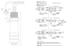
I know nothing about the PLC side, but I'm confused as to why you think the transmitter wiring is correct. There's a wiring manual with dozens of wiring diagrams,
http://www.te.com/commerce/Document...Installation-Wiring_AST&DocType=SS&DocLang=EN

but it is arranged by connection style, and does not refer to model numbers. In any event, I can't find a a 3 wire red/black/green combination.

The 3 wire voltage flying lead model uses Black/red/white wires
AST_Wiring_diagrams.jpg


From where do you determine your wiring connectionsfrom?
white wires
 

Similar Topics

If you are fusing a 4-20mA output from a signal isolator. What size fuse would you use?
Replies
3
Views
1,816
We have a bunch of signals that are differential 4-20mA inputs. I was wondering how can I measure the physical current using a Fluke 787 or a...
Replies
1
Views
1,463
Hi Guys, I was given a task to configure using level setpoint to have an output of 4-20ma equivalent using GE Fanuc 9070. Is this possible? If...
Replies
1
Views
2,050
if I have pflex 4 connected to compact logix L35E chassy. On this chassy, there is an analog output module 1769-OF8C(channel 0 is configured to...
Replies
3
Views
2,916
Hello everyone, I have a little problem converting a 4-20ma signal to display a temp, reading on a PanelView. I have a RTD wired into a...
Replies
9
Views
5,633
Back
Top Bottom