Mitsubishi GX Developer addressing help

geniusintraining

Lifetime Supporting Member + Moderator
Join Date
Jun 2005
Location
SC
Posts
8,274
Hello everyone,

Looking for a little help, I have a simple project but I have not done very much analog with Mitsubishi...

Its a Q06HCPU and trying to move (MOV) my analog input (slot 1) 64AD input 1 and input 2 to my analog output (slot 2) 62DA and can not figure out the addressing... [MOV xxx xxx]

2 inputs wired to 64AD and 2 outputs wired to 62DA, I would like to move the word or double word from one to another

{PS} {Q06H} {QX48Y57} {64AD} {62DA} {Ethernet} {CC LINK}

Thank you for your time :)
 
So getting back to this project and still having issues, not sure why this would not work, had a couple other people look at it and nothing, before I buy another card anyone have ideas?

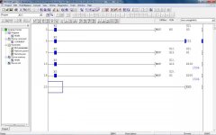
Im moving U1\G11 (analog input) to U2\G1 (analog output) also G11 to D100 so I could see the raw input 0-4000 and also moving G1 to D200 just to verify the value is getting there, I see G1 changing but I have nothing on the output

ladder.jpg
 
Hi did u config the card using GX Configurator?

Or are you trying the older method of from and to commands to access the slot /channel data
 
Hi did u config the card using GX Configurator?

Or are you trying the older method of from and to commands to access the slot /channel data

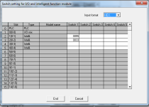
I have only setup the two pages above

rung 0 moving 0 to U2/G0 (enabling the card)
rung 1 setting Y21 to true (enabling CH1)
rung 2 Moving U1/G11 to U2/G1 (input 1 to output 1)
rung 3 and 4 just so I can see the value moving them to D100 and D200

So I guess to answer your question... no I dont think I have done either
 
So I ended up getting GX Works2 and gave up on GX Developer... I still do not think it needs to be this hard, even with Works2 it was a pain

If anyone is searching and finds this see attached program, works as intended and it should save you some setup time
 
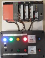
See pic below for the setup, note I have not configured the Ethernet or CC-Link modules in the program above... Thank you for the help (still not sure why the other program would not work)

analog_mit.jpg
 
Last edited:

Similar Topics

Hi One of the PLC's that I maintain/update is a Mitsubishi Q-Series, probably installed about 10 years ago. At the moment, ALL the wires from...
Replies
13
Views
1,169
Hi everyone, I'm working on a Mitsubishi Q series PLC whose code was developed in Mistubishi's GX IEC Developer v7.04. I looked online for GX IEC...
Replies
9
Views
1,468
Hi everyone, I'm working on a Mitsubishi Q series PLC whose code was developed in Mistubishi's GX IEC Developer v7.04. I looked online for GX IEC...
Replies
0
Views
496
On our system, on the HMI we've got a page of setpoints. These are the values at which alarms are set (e.g. a high temperature alarm or a low...
Replies
4
Views
1,235
On our PLC we've got a HMI where the operator can enter a target rotor speed in RPM. When target speed is enabled, M70 = TRUE. Then the operator...
Replies
19
Views
2,825
Back
Top Bottom