Mapping I/O to UDT's RSLOGIX 5000

electric101

Member
Join Date
Sep 2015
Location
Alabama
Posts
27
Greetings,
I'm here in my home lab trying to acquire a working knowledge of UDT's. I've had to work with them in the past in large existing programs and they were a pain to track down and find out what IO they were really controlling. I have a decent understanding of what they are and I've created several to play with here using my softlogix processor and a digital flex IO rack.
My issue starts when i'm trying connect my UDT's to the physical IO. it looks like I cant use a simple move instruction (which would be way too easy and exactly what I need) I have a flex IO 8 point output. Local:1:O.Data[0]
I have a UDT consisting of (see attachment)
Valve001
Valve001.Out
Valve001.Out.OPEN
Valve001.Out.CLOSE
Valve001.In
Valve001.In.OPEN
Valve001.In.CLOSED
I have a copy instruction set to copy Valve001 to Local:1:O.Data[0] Length 2
that allows the Out.Open and Out.Close UDT's to control bits 0 and 1 of the 8 bit output . .... great.
Now I have another UDT setup to control lighting...
Door
Door.Out.OPEN
Door.Out.CLOSE
I want to control bits 2 and 3
I make another copy instruction in a line before the original copy instruction that states Copy Door to Local:1:O.Data[0] Length 4
but i'm really just fighting for the same 2 bits that the valve controls.... how can I control bits 2 and 3 for the door/lighting logic using these UDT's?

and that's not yet getting into having physical inputs moved/copied to the UDT input bits.
thanks!!
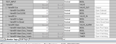
UDT1.PNG UDT2.PNG
 
You can't really do it this way. You may end up with memory overlaps and all out confusion. Nix the MOV instructions and just use simple XIC/OTE instructions. MOV/COP work fine when the source and destination tags are the same UDT. However in this case the Local IO doesn't match the UDT at all.


Valve.Out.Open Local:1:O.Data[0].0
-----| |-----------------( )-----

Valve.Out.Close Local:1:O.Data[0].1
-----| |-----------------( )-----

 
Greetings,
I'm here in my home lab trying to acquire a working knowledge of UDT's. I've had to work with them in the past in large existing programs and they were a pain to track down and find out what IO they were really controlling. I have a decent understanding of what they are and I've created several to play with here using my softlogix processor and a digital flex IO rack.
My issue starts when i'm trying connect my UDT's to the physical IO. it looks like I cant use a simple move instruction (which would be way too easy and exactly what I need) I have a flex IO 8 point output. Local:1:O.Data[0]
I have a UDT consisting of (see attachment)
Valve001
Valve001.Out
Valve001.Out.OPEN
Valve001.Out.CLOSE
Valve001.In
Valve001.In.OPEN
Valve001.In.CLOSED
I have a copy instruction set to copy Valve001 to Local:1:O.Data[0] Length 2
that allows the Out.Open and Out.Close UDT's to control bits 0 and 1 of the 8 bit output . .... great.
Now I have another UDT setup to control lighting...
Door
Door.Out.OPEN
Door.Out.CLOSE
I want to control bits 2 and 3
I make another copy instruction in a line before the original copy instruction that states Copy Door to Local:1:O.Data[0] Length 4
but i'm really just fighting for the same 2 bits that the valve controls.... how can I control bits 2 and 3 for the door/lighting logic using these UDT's?

and that's not yet getting into having physical inputs moved/copied to the UDT input bits.
thanks!!

You could do this with MVM (Masked Move) instructions instead of COP instructions, but it's not very tidy. A better way.....

If you make your Valve handling code into an AOI (Add-On Instruction), then you can map the Inputs and Outputs directly into the AOI - there is no need for the I/O data to be stored in a UDT tag unless you need them there. If you do need them in the UDT tag, pass it to the AOI as an In/Out parameter, and map them to the UDT tag inside the AOI using XIC/OTE's as already suggested.

If you go this route, make your alarm timers as Local tags to the AOI, and pass in the presets as DINTs - you'll need a couple of MOVs in the AOI to load these values into the local timers' .PRE registers.

EDIT : If you do use AOI for your valves, you will create an AOI tag for each instance call - this is, in effect, your Valve UDT tag, and the AOI code will map the I/O to the AOI tag automatically..... If you want an example, just shout....
 
Last edited:
You can't really do it this way. You may end up with memory overlaps and all out confusion. Nix the MOV instructions and just use simple XIC/OTE instructions. MOV/COP work fine when the source and destination tags are the same UDT. However in this case the Local IO doesn't match the UDT at all.


Valve.Out.Open Local:1:O.Data[0].0
-----| |-----------------( )-----

Valve.Out.Close Local:1:O.Data[0].1
-----| |-----------------( )-----


I do the above....Your technicians will appreciate it....or hate you for using MOV or MVM instructions if you go the other way.
 
I do the above....Your technicians will appreciate it....or hate you for using MOV or MVM instructions if you go the other way.

And as a developer, it means I can get a bunch of programming completed/tested before the electrical work is even completed. Once I have the final electrical IO list I can use some fancy Excel VBA to auto-generate IO mapping logic and just import it into the program.

Everyone's happy:beer:
 
I use AOI's - technicians love it because if one plant item alarms they can leave the programming laptop in the cupboard - it won't be a problem inside the PLC.

I give as much info as possible about what caused the alarms, by having multiple alarms for each plant item/device..

e.g. for a Valve...

A warning - "Slow/Opening" or "Slow/Closing" = it got there, but outside normal operating time. could indicate an air problem, a mechanical problem with the valve. etc.

An error - "Fail Opening"/"Fail Closing" = it never made the requested position limit switch after the "grace" time elapsed. usually a switch/sensor failure, or a wire-off etc.

... just examples, you can do just about any error checking you want, and it is compact because the same code runs for as many plant items as you need. Properly developed and tested, the AOI also protects against the "fiddler" technicians, because it can't be changed online. You do have the ability to view the code for each instance, but that would be a rare necessity. All the "debugging" information is present on the fronts of the I/O modules.
 
I use AOI's - technicians love it because if one plant item alarms they can leave the programming laptop in the cupboard - it won't be a problem inside the PLC.

I give as much info as possible about what caused the alarms, by having multiple alarms for each plant item/device..

e.g. for a Valve...

A warning - "Slow/Opening" or "Slow/Closing" = it got there, but outside normal operating time. could indicate an air problem, a mechanical problem with the valve. etc.

An error - "Fail Opening"/"Fail Closing" = it never made the requested position limit switch after the "grace" time elapsed. usually a switch/sensor failure, or a wire-off etc.

Yep....I also have, both inputs made (open and close simul which usually is a bad switch) and no inputs made (open and close after a time...stuck in middle).
 
Yep....I also have, both inputs made (open and close simul which usually is a bad switch) and no inputs made (open and close after a time...stuck in middle).

Absolutely, there's very little you cant test for, some other things that I have done in the past...

A test for "unseated" - this is for valves that can be forced off their open or closed positions due to excessive pressure in the pipework, this has proved useful on many occasions, leading to sequence or even pipework modifications to solve the issue.

A "commission" mode - this "learns" the typical time for the plant item to respond, and uses that as a basis to seed the grace timer presets.

A "predictive" status that tells you if a plant item is getting slower to operate (typically used on valves, but can also be used on many devices). This can lead to the plant item being checked out when it is convenient, rather than when it fails in the middle of a batch.

A "maintenance" mode where the plant item feedbacks are simulated internally. This allowed a batch to be completed even with a faulty plant item.

The list can go on and on, but the point is that once the code is developed for each type of plant item, stick it in an AOI and re-use it in every project, even if you don't use all the functionality in all projects, you know the AOI was tested for all eventualities and doesn't need to be tinkered with.
 
Last edited:
I've been doing the I/O moves lately in ST

I find it's easier to repeat and rename for speed. I really like the idea of using excel and vba to generate this code though!

in ST it would look like:
Code:
Local:1:O.Data[0].0 := Valve[FONT=courier].Out.Open; //handle output[FONT=courier][FONT=courier]
Valve.Opened := Local:2:I.Data[0].0;[/FONT][FONT=courier] //handle input[/FONT][/FONT][/FONT]
 
If you do use AOI for your valves, you will create an AOI tag for each instance call - this is, in effect, your Valve UDT tag, and the AOI code will map the I/O to the AOI tag automatically..... If you want an example, just shout....
Daba, would you mind passing on that example? I am looking into learning about/creating such AOIs for our system and just came across this thread. This would be most helpful. Thanks in advance.
 
You can't really do it this way. You may end up with memory overlaps and all out confusion. Nix the MOV instructions and just use simple XIC/OTE instructions. MOV/COP work fine when the source and destination tags are the same UDT. However in this case the Local IO doesn't match the UDT at all.


Valve.Out.Open Local:1:O.Data[0].0
-----| |-----------------( )-----

Valve.Out.Close Local:1:O.Data[0].1
-----| |-----------------( )-----


+1 It's the simple and clear way to do it. I'm no fan of AOIs in general, and using one just to map I/O seems a bit silly.

Like I told a GM director once, think PLC, not PLC++
 
+1 It's the simple and clear way to do it. I'm no fan of AOIs in general, and using one just to map I/O seems a bit silly.

AOIs are spectacular when used properly, I've added a lot of functionality to valves/motors/analogs because of this, and have a very useful library of functions and no hassle of using them.

For clarification, you would not create an AOI to map the IO, in my example I could place Local:1:O.Data[0].0 directly on the valve AOI parameter of "Open". It's extremely obvious and just a matter of preference really.
 

Similar Topics

Hi everyone, Kind of new at this, so we recently upgraded our 1769-l32e to the newer 5069-L320erm, i converted the file over and Verify the...
Replies
8
Views
391
Hello Guys I have an 1756-L73S Controller with a Fanuc Robot mapped as follows: - In 1756-EN2TR Slot 2 the Fanuc Robot is defined as an...
Replies
5
Views
235
This has been on my mind for a while now, wondering if anyone here has any best practices or insights. I have been working with a plant that has...
Replies
8
Views
536
Hi long time out... I´m in a project now, that request to upgrade an old SLC to a new ControlLogix. Just the PLC. It is connected now to a...
Replies
5
Views
1,945
Hi all, I'm really new to this. I need to export the Modbus register mapping from a Modicon M580 through Control Expert for the registers that...
Replies
4
Views
930
Back
Top Bottom