Real Time Clock issue on Micrologix 1100

melicha8

Member
Join Date
Dec 2016
Location
Woodland
Posts
4
Hello all,

Long time lurker first time poster. I appreciate all the advice you guys provide. I've learned a lot. I am seeking an answer to a problem that has just begun to pop up.

I have four growth chambers at work. We conduct trials on plant pathogens and we use Micrologix 1100 PLCs to control the environment. The contractor that built these did a really terrible job and I began revising the code to get our chambers to work more effectively with tighter deadbands for Temp*C and Relative Humidity. I finished the programming a couple months ago and they have worked flawlessly.

Just this past week however a problem emerged with the real time clock. The lighting program that controls the day length in the chamber is not turning off/on the lights. There is a chance it is just affecting the whole program in general because the diurnal setpoints used to promote innoculation and establishment of plant pathogens on our experiments are also controlled by the RTC function. Many of the experiments right now are set to have the same day and night temp/RH setpoints so the lighting caused us to discover the problem first.

The problem so far as I can tell is the RTC stops advancing a few hours after I reset it in the function file. When I returned in the morning I took some screen shots. What you see in the images below are what are causing the lights to stop working. When I go live I see that the RTC hour and minute values do not have a value at all. They read 0. I will look up the values of the function file and the boolean value on the Disable bit status is 1 and none of the other fields have a value. I can reset the RTC very easily and it will work for half a day but when I come back the next day it is back to the same problem. There is no alarm getting triggered to indicate the battery is low. This is happening on only 2 of the four chambers and hadn't done anything like this for about 3 months so I really don't know where to go from here. I would appreciate any help you could provide.

*edit image explanation
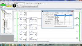
RTCError-Rungs utilizing RTC values show a null value. Image is not the lighting program but the program that handles day and night modes
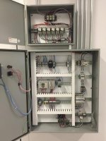
RTCFunctionFile-This is how the function file looks when I connect after the lighting program fails to turn on or off
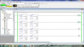
RTCFunctionFileGood-This is the function file from a working chamber
RTCError.jpg RTCFunctionFile.jpg RTCFunctionFileGood.jpg
 
Last edited:
This is very unusual. You could zip and post the .RSS file for us to have a look at but as long as the RTC.X words aren't being written to in the program anywhere I would guess that you have a rare case of a faulty RTC in the processor. Especially since it completely disables itself like that.

The RTC chips I've had experience with in the past completely reset themselves on a battery failure. I've never taken apart a ML1100 so I can't tell you if the same battery is used for the PLC memory and the RTC but perhaps it isn't. It might be worth taking apart to have a look and see if there is a coin cell in there, and if so replacing it. If there isn't you may need a new ML1100.
 
I checked the AB Knowledgebase and found 519752 - MicroLogix 1100 Real Time Clock (RTC) reset on power cycles.

Are there power issues in your situation, or is the controller power being cycled at all? The article basically says check for proper grounding because electrical noise could be to blame.
 
Here is the code. Feel free to critique any other part of the program. I have been limited with the touchscreen interface since I don't have the Maple Systems program to edit and load a new touchscreen file so I'm working with what the Refer company already had configured
 
melicha8,

What type of lighting is being controlled by the plc? Specifically is it a ballast operated type lighting? Also...how are the lights switched by the PLC? Are the lights wired directly to the outputs?....or is there an output relay that switches the power to the lighting system.

Power noise from within the power system to the PLC can disrupt the RTC, and often noise comes from ballasted lighting systems.

"The only condition under which the firmware will disable the RTC without user intervention is if enough external noise gets into the controller, it can prevent the microprocessor from being able to successfully read the clock chip even after a set number of retries, and so the firmware disables the RTC.

Items to verify:

Check is for proper grounding of the controller.
Check what else is being power cycled at the same time as the controller. If he power cycles the controller by itself, does it disable the RTC, or only if it is power cycled at the same time as everything else in the panel? It's possible that the noise is occurring because of the external devices that are powering down at the same time as the controller."
 
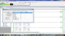
Here is the image of the panel. The chamber contols 6 banks of 9 T8 fluorescent lights. One electromechanical relay controls a bank of lights. The relays are located in the top enclosure. These outputs are controlled by the PLC. The output expansion module operates the remaining outputs 2 AC coils for cooling, 2 coils for dehumidification, The lower right relay operates the humidifier, 1 output for a high temp indicator LED/alarm, and the last output operates the resistive element heater. That would be the set of SSRs attached to the massive heat sink on the bottom right as well. These have been commissioned for about two years now. They have not worked for other reasons(if you want to see some terrible code I can post it). As I said before in the configuration they are in now they worked for a few months no problem. The only modifications I made was eliminating the same spec electromechanical relay that was running the heater. I installed the Crydom SSR's because the old ones melted in their sockets because they were functioning near the limits of their rated current

edit: could the proximity of the solid state relays to the ground point cause the interference?

panel.jpg
 
Last edited:
I suspect that you already have the answer (ground noise).

You might benefit from having a line filter on the AC power going into the PLC (assuming it is a 120vac powered ML1100).

Style critique: It would be wise to use integers against integers when checking for equality. You are using Floats compared to Integers (the RTC:0 elements are integers starting on rung 2:8) which should work unless you happen to end up with a value in your float that cannot be represented exactly as a whole number. In this application it may not be possible for that to happen, so this is just a style critique really.

You may want to add some ladder code to monitor the RTC:0/DS bit and set an alarm so that you can capture when this occurs if it keeps haunting you. I believe that this bit is not writable from ladder code, so you should only be able to change its state by using RSLogix software to disable it with the Function File "Disable Clock" button.
 
I can't tell from the picture- where are your grounds for the panels? I see the PLC which appears to be grounded to a DIN-rail grounding block, but what about the main ground that ties the panel to earth?
 
I suspect that you already have the answer (ground noise).

You might benefit from having a line filter on the AC power going into the PLC (assuming it is a 120vac powered ML1100).

Style critique: It would be wise to use integers against integers when checking for equality. You are using Floats compared to Integers (the RTC:0 elements are integers starting on rung 2:8) which should work unless you happen to end up with a value in your float that cannot be represented exactly as a whole number. In this application it may not be possible for that to happen, so this is just a style critique really.

You may want to add some ladder code to monitor the RTC:0/DS bit and set an alarm so that you can capture when this occurs if it keeps haunting you. I believe that this bit is not writable from ladder code, so you should only be able to change its state by using RSLogix software to disable it with the Function File "Disable Clock" button.

Thanks OKiePC, I'm aware of the data type comparisons, I started in C, those are an artifact of the previous programmer. I'll see what I can do to clean them up.

I wish I had the Weintech HMI software because I could send the Disable bitstate to the alarm page that is already setup. Maybe a workaround, and it wouldn't be good code in the long term, is I can utilize the low battery alarm the HMI already reads and just change the bit address. I wouldn't be able to change the name of it but just for troubleshooting it would work. The bitstate for a low battery alarm already appears on the little LCD display.

I can't tell from the picture- where are your grounds for the panels? I see the PLC which appears to be grounded to a DIN-rail grounding block, but what about the main ground that ties the panel to earth?

rupej, The ground lug is located down next to the heat sink. The main ground connects to the set of lugs and the din rail grounds and the power supply ground also runs to the same lug. Question tees up my follow up question. So I took everyone's advice on trying to track down possible causes of EMI. The first rabbit hole I went down to eliminate the problem was I started cutting power to various loads. It turns out the first load I cut power to was the heater circuit made the RTC problem disappear. It's been going a few days now and the lights are cycling according to the input values. The disable bit is still zero.

So assuming the cause is the heating circuit and I'm not getting some kind of false positive. The heater is a resistive load switched by the SSRs. The heaters operate on 208V. I am switching both legs of the load off which is why there are two. Each is capable of switching of 25A. A couple of questions that will help inform me of how to fix this:
1) Could the proximity of the heat sink to the ground lug be the source of the EMI? Would I be able to attenuate it by isolating the heat sink from the panel(it is currently self tapped to the standoff panel)?
2) Is the EMI likely to be conductive or radiated given the type of load?
3) If these variables are known(by you?) what would be the best course of action? a)move the heat sink and SSR's b) install an AC line filter(high pass low pass?) or c)something else

Thanks gentlemen you've been a big help.
 

Similar Topics

I have a 2711-K10G8 with a Real time clock issue. I get error 32 on boot-up. I replaced the real time clock with a new one, but I still have the...
Replies
2
Views
1,879
Hello. This is one for the Mitsubishi experts. I need to measure the time for a remote device's to return process data sent from the i-QR...
Replies
17
Views
2,114
Hi all I thought I had this working but upon doing a checkup a few months after the machine was commissioned, I found that adjusting the RTC via...
Replies
4
Views
1,845
hi all i have used a real time clock to turn on a bit after 1 month. the plc was off for this whole month and when i turned on the plc after a...
Replies
2
Views
1,417
hey, anyone know how to export time from panelview 800 to micro 850 and to compare time? or distinguish various time , like to know which shift...
Replies
1
Views
1,441
Back
Top Bottom