Hi All and a Happy New Year,
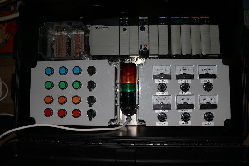
I have been a long time reader but this is my first topic. Early last year after having previously passed my Controllogix Certificate Program with Rockwell at my own cost I decided to make my own Rockwell simulator box to keep my hand in on everything I learnt on the courses (see pic below).
 https://flic.kr/p/QM8Gb9
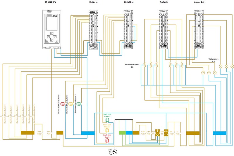
Due to the cost of these courses I am creating a Siemens version of my simulator box as the other half thinks this would be cheaper than the Siemens courses to learn on with all the available documentation that can be found online.
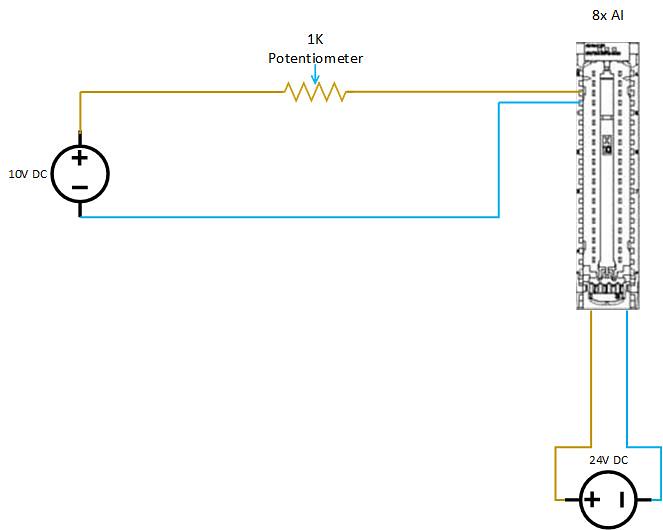
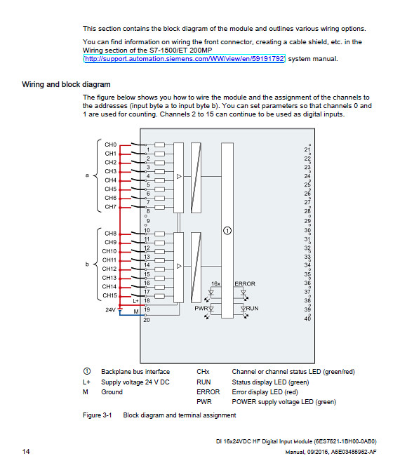
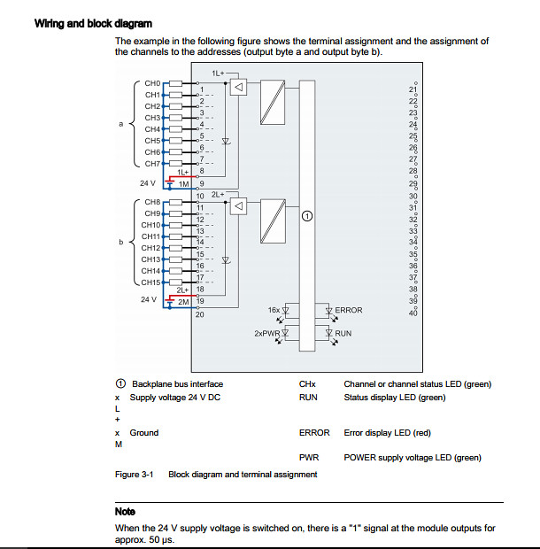
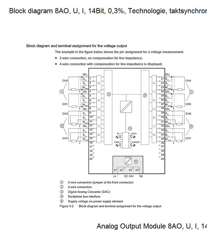
I am just wondering if anyone out there in the know would be able to look at my wiring diagram as well as the official wiring diagrams all posted below to tell me if I have done anything incorrectly as the official wiring diagrams display the power out to each sensor coming from the pins in the input modules and the same for the commons on the outputs returning to the modules whereas I would like my projects sensors to be powered outwith the modules and vice versa on the common wiring to save on wiring. Hope this makes sense! thanks
 https://flic.kr/p/QMcufs
DI16x24VDC
 https://flic.kr/p/QMbNDd
DO16x24VDC
 https://flic.kr/p/QQCDLT
AI8x10VDC
 https://flic.kr/p/QBzc7S
AO8x10VDC
 https://flic.kr/p/QBzaLf
thanks for your time!
cheers Callum
I have been a long time reader but this is my first topic. Early last year after having previously passed my Controllogix Certificate Program with Rockwell at my own cost I decided to make my own Rockwell simulator box to keep my hand in on everything I learnt on the courses (see pic below).
https://flic.kr/p/QM8Gb9Due to the cost of these courses I am creating a Siemens version of my simulator box as the other half thinks this would be cheaper than the Siemens courses to learn on with all the available documentation that can be found online.
I am just wondering if anyone out there in the know would be able to look at my wiring diagram as well as the official wiring diagrams all posted below to tell me if I have done anything incorrectly as the official wiring diagrams display the power out to each sensor coming from the pins in the input modules and the same for the commons on the outputs returning to the modules whereas I would like my projects sensors to be powered outwith the modules and vice versa on the common wiring to save on wiring. Hope this makes sense! thanks
https://flic.kr/p/QMcufsDI16x24VDC
https://flic.kr/p/QMbNDdDO16x24VDC
https://flic.kr/p/QQCDLTAI8x10VDC
https://flic.kr/p/QBzc7SAO8x10VDC
https://flic.kr/p/QBzaLfthanks for your time!
cheers Callum