modbus communication in PLC k120s

kurobima

Member
Join Date
Dec 2016
Location
Salatiga
Posts
10
hallo,, my name is Bima, I'm a student & now I'm studying modbus communication in PLC. I use the master-k120s from LG. I learn from the manual book, but there is so much I don't understand. is there anyone who can help me? maybe some reference?
Thank you ^_^
 
thanks for your reply gclshortt ^_^ I have watch that video too, that's very helpful.
is there any other references? maybe some reference about modbus communication in PLC K120s in spesific?
 
Some things they don't tell you in the Modbus manuals.

A field device, like a VFD or a single loop controller is always a slave/server. An HMI is usually a master/client. HMI software can sometimes be either a master/client and a slave/server.

The slave will have data assigned to specific registers in a map/table of registers/addresses. The slave setup is
- serial comm (baud rate, number for data bits, stop bits) or IP addressing
- a unique slave ID address.
Beyond that, there isn't much to configure for a slave for read actions.

Sometimes a preliminary action is needed to write a value to a device, like some bit needs to be set first,then a write action will be valid (device specific)

The serial comm settings for both devices (RS-485/RS-232) need to be identical (word size 8 bits, one stop bit, parity) on both devices. Modbus RTU is 8 bit data word, Modbus ASCII is 7 bit data word.

Modbus RTU is typically done over RS-232 or RS-485. It is common to refer RS-485 as '2 wire', but in reality a 3rd wire, a signal common, should be used, too, so it's really 3 wire.

The RS-485 data lines go by various designations, A/B, (+)/(-), D/D-. Functionally negative is wired to negative, positive to positive, if the labeling is the same. However, different manufacturers label differently. Sometimes the (+) needs to go to (-). It won't damage the line drivers if it is connected backwards, but it won't work. This is a major issue when connecting devices from different manufacturers.

Termination resistors usually are not needed at 9600/19.2K baud rates on the bench, but might be needed at faster rates or longer distances.

Some devices don't 'see' comm setting changes unless power is cycled for a cold start.

Modbus just carries bits. It doesn't know or care what the bits mean. It is up the application level firmware/software to interpret what the bits mean. This is important in interpreting data formats.

32 bit Floating point values can be troublesome because there are four IEE754 formats for byte/words, two of which are commonly used, the others rarely if ever. If the device interprets using the wrong format, then the value 174.9 appears at -5.937856^23 because the correct format is the 'other' one.

Integer format frequently uses an implied "multiplier". The integer value 15372 needs to be multiplied by 0.01 to get the correct value 153.72. The documentation usually notes when this is the case.

The leading numerals 3 or 4 used for register/addresses like, (3)0032 or (4)00712 is as a convention so human beings can identify whether to the register is an input register (starts with a leading numeral 3) or a holding register (starts with leading numeral 4). Although the leading numeral 3 or 4 is NOT used in the modbus message, many master/client use the leading numeral to define which Function code is to be used. (4)00321 would use Function Code 03, which reads a holding register.

Ironically, function code 03 is used for (4)xxxxx holding registers, while function code 04 is used for (3)xxxxx input registers. No one knows why. It just is.

If you can test a setup on the bench, it's easier than testing in the field because of issues over long distance cabling, but you do what you can.

I always test a slave first with a generic PC Modbus master, like Modscan32, to make sure I can establish communications by reading some non-zero register, confirming that its correct; then writing a value. I try to test with a holding register, in order to avoid the complication of reading the wrong register but getting a valid reply that is zero, because sometimes zero is a filler for empty registers. For coils or discrete inputs you've got 50% chance of getting the right value from the wrong register, given that the value can only be a one or zero. But a temperature value is not likely to be the same value as the Hz value.
 
wow... there really is so much to learn about modbus communication. I'm trying to connect PLC k120s with an inverter LS sv-ic5. I can operate the inverter from PC with DriveView, so I think the modbus connection is working, so I'm wondering if I could operate it with PLC, like change the parameter or etc. is it possible?
 
wow... there really is so much to learn about modbus communication. I'm trying to connect PLC k120s with an inverter LS sv-ic5. I can operate the inverter from PC with DriveView, so I think the modbus connection is working, so I'm wondering if I could operate it with PLC, like change the parameter or etc. is it possible?

Yes. We use Micrologix 1400 PLCs to control LSIS H100 VFDs. We don't try to modify all parameters over the RS485 network, but will adjust speed, accel, decel and the command word and monitor 8 parameters from the VFD using read and write messages in the PLC.

You will need to program the VFD to allow the speed and command words to be derived from the Comm channel, and set the Comm parameters to match those in the PLC (baud, parity, stop bits). Each device needs a unique Modbus ID.

Look at the VFD parameters:
DRV 06 = 3 = "Command Source 3 = Communication port"
DRV 07 = 6 = "Frequency Source 6 = Communication port"

COM 01 = "Modbus ID"
COM 02 = 0 = "Modbus Protocol"
COM 03 = "Speed (4=19.2k)"
COM 04 = 0 = "Frame settings: 0 = 8 data bits, no parity, 1 stop bit"
COM 05 = "Response Delay ms (100 works well for us)"
COM 30 = "Output Parameter Count (we want to read 8 values, your application may be different)"
COM 31 = 000A = "First parameter to poll at Modbus address 40256 000A = Output Frequency"
COM 32 = 000E = "2nd parameter to poll at Modbus address 40257 000E = Operation Status Bits"
COM 33 = "3rd parameter to poll at Modbus address 40258"
COM 34 = "3rd parameter to poll at Modbus address 40259"
etc for more than four words to be read by your PLC.

COM 50 = "Input Parameter Count...words to be written by the PLC as inputs to the VFD"
COM 51 = 0005 = "0005 = Command Frequency"
COM 52 = 0006 = "0005 = Operation Command Bits"
etc if using more than 2 input parameters.

Also review parameters:
PRT 12 = "Speed Command Loss action...what happens if comms stop?"
PRT 13 = "Comm Timeout Seconds...how long until the drive executes the action in PRT 12"
 
hhmm,,, from what I see, the Micrologix 1400 PLC is too different from k120s, so I don't quite understand it ^_^
have you ever use k120s? my campus only have k120s from LS & Thinget.
 
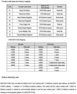
https://www.google.ca/url?sa=t&rct=j&q=&esrc=s&source=web&cd=1&cad=rja&uact=8&ved=0ahUKEwi4zai13cvRAhXk54MKHTrlA5UQFggcMAA&url=http%3A%2F%2Fwww.atcplc.com%2F%3Fdownload%3Dmodbus-map%2520LG%2520Master%2520k.pdf&usg=AFQjCNGc_SOzEUbwUlX1vUFHtnJkUeOUqA

I would start to play with the unit. The K120S has Modbus RTU. I am not sure of your serial port (RS485, RS232 ...) but I would connect this to your computer. Run a program like AdvancedHMI.
https://sourceforge.net/projects/advancedhmi/
This program is free and has the drivers for Modbus RTU.
Look at the Modbus Memory map from the above manual and read some data to determine communication.
This will guide you through installing and running AdvancedHMI.
http://accautomation.ca/create-a-plc-with-hmi-training-and-learning-environment-free/

Regards,

K120S Modbus Map.jpg
 
I tried to connect the rs485 port from the PLC to the one in the Inverter with two wire. then with KGLWIN I made the ladder like in the manual & changed the address a little. I want to know whether the data can be sent or not, but I didn't find any change when I look at the monitoring mode.
 
What we're missing is exactly what you've done.

What the serial settings are, what the slave ID is, which data you are trying to read, what format the data is, what function code you're trying to use, how you enabled the modbus port, among others.

What's the URL for the drive manual with the Modbus map?

Have you tried a generic Modbus master, one of the freebies? With those, one sets up serial comm, defines a Function code and an address and expects to get a reading, without programming.
 

Similar Topics

Apologies for not being the best IDEC programmer. I recently was doing some inspections on a site that had 3 FC6A IDEC processors. The issue is...
Replies
0
Views
74
can i send and recieve data using my yokogawa UT35A controller with my siemens s7 1200 plc using profinet communication without using gsd file
Replies
1
Views
381
Hi hope all are ok. I have mitsubishi PLC Q03UDV CPU. I have control a drive through modbus inteligent module QJ71MT91 in GX Works2. Any experts...
Replies
1
Views
604
hi, so anyone know how to connect a haiwell HMI with XINJE PLC by using MODBUS communication protocol? please help me ASAP. thank you
Replies
9
Views
2,866
Hi all, Has anyone dealt with Modbus RTU communication using SE`s Machine Expert? I have got the modbus tcp working, but not used the serial...
Replies
1
Views
1,210
Back
Top Bottom