Cntrlx 1756 - L62 MSG with Digi One

cabbie27

Member
Join Date
Jan 2017
Location
hamilton
Posts
6
Currently having an issue trying to set the path with a Control Logix 1756 Plc - l62. Trying to get it to talk with a Digi One. I have set the Digi one up for Ethernet Ip and with a static Ip address.
I though I could just set the path in the msg instruction as
2, INSERTIPHERE

My digi one shows up in Rslinx with the appropriate Ip address.

Any help is greatly appreciated.
 
Explicit Path Specification....

Port, Destination, [Port, Destination] : repeat as necessary.

So the first thing in your ControlLogix MSG path would be ..

1, go out of the backplane port...
n, to the comms module in slot n (ENET, ENBT or EN2T = ENxT)

Then ...

2, go out of the Primary port from the ENxT...
192.168.1.123, to destination IP address

I'll assume it stops there for your Digi One. If it were specifying the path to another ControlLogix controller, the path would then need...

1, go out of the backplane port of the remote ENxT...
y, to slot y (where the CLX controller resides.

Going back to your Digi One, I expect the path needed would therefore be ...

1, n, 2, aaa.bbb.ccc.ddd

where n is the slot number of your ENxT module, and aaa.bbb.ccc.ddd the IP address of the Digi One.
 
Welcome to the forum!

That path will work with certain models of Compact Logix, because the ethernet port is integral to the PLC, and is designated as port "2".

The Control Logix is a whole different beast. The ethernet module will be in a different slot to the PLC.

Think about it this way. You have to get the message from your PLC's "brain", onto the chassis backplane, into the ethernet card's "brain", out the ethernet port on the front of the ethernet module, and then into the Digi One. Each of those "hops" require you to direct it on where to go.

Step 1: PLC to Backplane. Off the top of my head, I think the "backplane" port is 0. (correction: 1)
Step 2: Backplane into ethernet module. What slot is the ethernet module in? If it's Slot 5, your next hop is "5".
Step 3: Out the ethernet port on the ethernet module. Again, from memory, I believe that all of the Control Logix ethernet modules have the ethernet port as "1". (correction: 2)
Step 4: into the Digi One. This is where you set your IP address.

So, if my memory of all this is correct, your path would be 0,[ethernet card slot number],1,[IP address]. (correction: 1,[slot],2,[IP address]) Give that a try and see how you go.

The Compact Logix is much simpler, because all you have to do is point it out the onboard ethernet port (2), and into the Digi One (IP address).

[edit] daba is quicker than me, and has a better memory for port numbers :)
 
Last edited:
daba is quicker than me, and has a better memory for port numbers :)

It's not memory as such, I actually teach this stuff.

One thing I didn't mention is that the programming software will replace any part of the path it knows about ....

An example will help here...

Suppose you have added the ENxT module in slot 4 to your I/O configuration and given it the name "ENxT_4"

The software will replace the first pair of port specifications 1,4 with the name ENxT_4

Suppose you then add the remote ENxT module as a child to the local ENxT, and give it the name "Rem_ENxT", then the software will replace the whole of the path specification so far with Rem_ENxT.

Suppose you now add a remote ControlLogix processor in the remote chassis, and name it "Rem_CLX"

The software will name the whole path Rem_CLX.

In other words, the "Path" to Rem_CLX is defined by the build of the IO Configuration.
 
True - and if I recall correctly, there's a "cheat" way to set up message paths leveraging this functionality - just add the equipment to the I/O tree as a generic ethernet module with the correct IP and any other parameters you want. Then you can browse to and select this module in your MSG setup dialog. Delete the generic module once you're done, and what's left in your MSG configuration dialog will be the path as described above.
 
True - and if I recall correctly, there's a "cheat" way to set up message paths leveraging this functionality - just add the equipment to the I/O tree as a generic ethernet module with the correct IP and any other parameters you want. Then you can browse to and select this module in your MSG setup dialog. Delete the generic module once you're done, and what's left in your MSG configuration dialog will be the path as described above.

Yes, indeed, I've done that in the past, but it only takes you to the point where the MSG leaves the local chassis, you still have to complete the path to the target device.

Every ControlLogix path starts 1,n ** where n is slotnumber of the comms module. That's easier to remember and quicker to execute than adding a module to create the path, then deleting it...

** Unless you are communicating via the Primary port, RS232 or USB depending on the controller.
 
Yes, indeed, I've done that in the past, but it only takes you to the point where the MSG leaves the local chassis, you still have to complete the path to the target device.

Are you sure? That's the whole point of adding the temporary module - you no longer have to complete the path. You will already have the path out of the local chassis set up by virtue of having all your chassis modules defined in the hardware configuration, so that part of it is taken care of whichever way you go - it's only once it leaves the local chassis that the "cheat" way is of any help.

I just added a generic ethernet module to an L73/EN2T chassis and set it up just like that...

Screen Shot 2017-01-24 at 10.20.38 am.jpg
 
Every ControlLogix path starts 1,n ** where n is slotnumber of the comms module. That's easier to remember and quicker to execute than adding a module to create the path, then deleting it...

True - although that's only a help if you do it often enough for those numbers to stick in your memory! But then again, if you don't do it often enough to remember it, the extra few minutes to add a generic device to your tree every once in a blue moon to help jog your memory aren't going to hurt :)
 
Are you sure? That's the whole point of adding the temporary module - you no longer have to complete the path. You will already have the path out of the local chassis set up by virtue of having all your chassis modules defined in the hardware configuration, so that part of it is taken care of whichever way you go - it's only once it leaves the local chassis that the "cheat" way is of any help.

I just added a generic ethernet module to an L73/EN2T chassis and set it up just like that...

"Completing" the path is usually the hardest part, considering that the majority of paths start 1,slot,2,.... and I'm not just talking about Ethernet paths...

Here is a perfectly legitimate path specification.

1,4,2,26,1,6,2,10.1.200.5,1,9,2,44

... and not too unusual either.

EDIT : I've seen worse : admittedly usually only a temporary solution until project completion, but nevertheless used.
 
Last edited:
So I believe I have set up the path correctly.
My ENBT is named (ENET)
So my path is like this
(1,4,2,123.123.123.123)
When i click apply the 1,4 changes to enet
so ENET,2,123.123.123.123
However once im done i get an error with illegal command from processor.
Im using CIP Source ID with a Node of 2.
Any ideas?

I also added an gen enet module than deleted it and i get same path as listed.
 
When configuring the path, the software will "echo" it below the entry box, if, and only if, the path is "valid". It's a good cross-check.

Now back to your issue....

What does your MSG "Configuration" tab look like ? can you post a picture....

Also tell us what you are trying to communicate with via the Digi One
 
Last edited:
DIGI -> Laser(RS232)
Bench tested with a compact logix processor through digi to rs232 device without any issues.
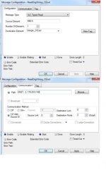
In the field using cntrlogix used same setup for msg just changed path but having the issues. Heres the msg instruction attached

msg.jpg
 
That all looks OK.

There's an unapplied edit on the Communication tab (shown as an asterix after the tab name).

Also that message isn't showing any errors....

Q1. How are you triggering the message ?

Q2. You are certain the SLC is Node 2 ?

Q3. If that configuration worked with a CompactLogix on the bench, what was the "Path" used for that message ?
 
Blocked Ip for security...

1)Triggered via timer.
2) Yes I double checked. I have also set the digi to accept all nodes but no luck either
3) Config worked with compact logix path was(2,IP)
however with compact logix there was no network switches in between. Verified all firewalls through switches as well as port settings and traffic. No issues their.

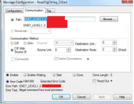
msg2.png
 
I'm not getting any error here on my L62...

OK, I know the message won't complete, but it's not indicating an "illegal command"

What's the data-type of the receiving tag ?

Also was the CompactLogix talking to the same SLC ? I'm thinking that that error message indicates the RS232 port on the target SLC isn't set for DF-1 protocol

Can you PING the Digi-One from the ControLogix location ?

I'm assuming you have set the Digi-One for DF-1 protocol >
 
Last edited:

Similar Topics

Hi all I have a ControlLogix 1756-L71SP that i want to use for general PLC applications, not safety. I am running Studio5000 v33, i can't...
Replies
1
Views
11
Hi, I have a ControlLogix system with 1756-IF16 analogue inputs. I can't scale the inputs at the card as there is a requirement to facilitate...
Replies
13
Views
300
Hi, I have two quick questions: 1- Could I use 1756-IA16/A with TTL inputs? Sourcing (PNP)? Sinking (NPN)? Either one? 2- What does /A in the part...
Replies
6
Views
151
Hi all, installed on chassis A17 an A/I from Allen-Bradley , problem is what ever I do , all channels are sticked on value 39.9 and cannot change...
Replies
1
Views
143
Hi, Is it possible to for an RIO with Flex 5000 series module, e.g. 5094-AEN2TR, to communicate with an 1756-L72E processor.
Replies
1
Views
90
Back
Top Bottom