Rate My Safety

Join Date
Oct 2015
Location
alabama
Posts
30
Master Control Relay vs. E-Stop vs. Motor Control Relay

Good morning,

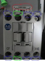
I'm trying to understand the purpose of the Master Control Relay vs. The E-stop vs. Motor Control Relay with regards to the safety standards in the US. I've attached a picture of the MCR I want to use. Below is a scenario I made, and I want to see if this entire setup is considered "safe" according to whoever in the real world would come to a plant / factory and check for these things, specifically in the USA.

/* Scenario Start */

From my understanding, you would take your 120 V coming into a panel, and first put it through a fuse.

Then, you take the wire out of the fuse and place it through an E-stop push button. From there you would go to empty terminals and also to a power supply to get 24 V.

Now, lets say you have motion coming from your PLC, like a basic servo drive and a pump (both single phase 120V). You would take your two separate outputs from your PLC that enable the motor and pump and go through two separate fuses. Then these wires go through the red circled terminals into A1 and out of A2 on the Motor CR (so you have one Motor CR for motor and one for pump). Now your Motor CRs are energized. You would not go through overload protection for the motor or pump, since you already have a fuse. You can for redundancy in safety only.

Now you take 120 V from one of your empty terminals and go through another fuse and go into one of the blue contacts on the Motor CR. So one wire rated @ 120V for the motor, and one wire rated @ 120V for the pump.

If the motor and/or pump was 3 phase, you would place each phase into it's own blue terminal. If motor / pump was 3 phase, you would include overload protection.

In the PLC Logic, you would write logic to turn the motor off when the E-stop is hit; and you would prevent it from coming on when you reset the E-stop to prevent too much voltage being drawn from the power supply at start up, similar to the 2nd picture attached. Your PLC would also lose power when the E-stop is hit, but when it starts back up, the motor will not start due to the logic written. /* Scenario End */


So I didn't use a Master Control Relay, only a motor control control relay and an e-stop for safety. I was not sure how to incorporate the Master Control Relay and exactly what function it serves, but If you could rate the safety of this according to the most up-to-date standard specifically in the US, and what else this panel needs for safety improvement, that would be excellent, thanks.
Capture2.jpg Capture3.jpg
 
I'm not sure where to start with this, but here are some initial thoughts.

1) First you must perform a Risk Assessment to determine the Performance Level required of your system. You must then design a safety circuit to meet or exceed this Performance Level. ISO12100 will detail the Risk Assessment process. ISO13849-1 will detail how to design your safety circuit.
2) You cannot perform safety functions in a standard PLC. If a PLC is used it must be a safety rated PLC with appropriate hardware.
3) Removing power from your PLC everytime you hit an E-Stop is considered poor practice. It is unnecessary and you will lose a valuable troubleshooting tool. For instance, you could monitor various E-Stop buttons and display on an HMI...unless the PLC turns off because you hit the E-Stop.
 
I'm not sure where to start with this, but here are some initial thoughts.

.

That was my exact thoughts, just wrong on so many levels that commenting would be a lengthy job, even from a UK standard.

OP, you need to appraise yourself of the standards to apply BEFORE designing anything, nobody can do that for you, you don't even mention what the machine is that you are controlling as that will effect the outcome.....
 
No one is forced to comment, ha ha. It's completely hypothetical. I've never built a panel from scratch on my own, so it's better to get input from experienced people. Any comments would be appreciated, but I'm really looking for in-depth analysis on the scenario.
 
Haha very funny. Actually I looked at some other posts on this forum, but I couldn't get a good understanding. That's why I made my own scenario, so If I know this works or does not work, then that would be excellent. The practices are different from country to country, so it's not right to assume those practices apply in US.

If you look at the searches from your google search, you can see those pages are outdated and old. Of course I checked google and I am still searching; I am asking many other people as well, not just this forum. I just posted here cause I know there are many experienced people here also, so whoever wants to put in the time to explain would have helped someone who really needs it! No effort would be wasted helping me, I'll promise that much.
 
Hasmi,
I believe that everything hd_coop said is exactly correct and should be your starting point.

The term MCR should probably be considered obsolete. It used to be used interchangeably with E-Stop relay but that was years ago before OSHA began requiring actual safety relays (re: PILZ).

Most manufacturers make some type of safety relay these days and have some good free literature/weblinks. Allen-Bradley (MSR138DP Safety Relay), PILZ (PNOZX2), etc.

Hope this helps.
 
hashmi.mohammad,

there's a lot to write and your understanding of the code is lacking, no offence meant.

All Machinery requires an E-stop, MCR, safety plc combination with reset sequence.

the e-stop(s) are wired in series with safety circuit devices and they go into the MCR or into the safety plc inputs.

when an estop is pushed, all I/O power is killed, inputs, outputs, servos, drives, motors, all pneumatic and hydraulics motion is stopped. DO NOT KILL THE PLC POWER. if the battery if bad, you could loose the program. the plc will be used to help trouble shoot what's wrong.
at reset, power is return the I/O power, all motion is still killed.
you must reset the machine in a safe manner.

Great, you are trying to learn.
I use the following materials.
NFPA 79 - Electrical standard for industrial machinery.
NFPA 70 - National electrical code
NFPA70E - arc flash
NFPA496 - purging and pressurization of electrical enclosures.

I would get NFPA 79 first
NFPA 70 - electrical codes for wiring second.

your question covers to much area for specifics because no machine is identical in regards to what safety items are required.

NFPA 79 is a good starting point.

james
 
I am a first time poster here but I am curious if you have a source for the I/O that must be turned off. It was my understanding that inputs were okay to keep powered on (help trouble shoot) while all outputs would need to be killed via an E-stop.


hashmi.mohammad,

there's a lot to write and your understanding of the code is lacking, no offence meant.

All Machinery requires an E-stop, MCR, safety plc combination with reset sequence.

the e-stop(s) are wired in series with safety circuit devices and they go into the MCR or into the safety plc inputs.

when an estop is pushed, all I/O power is killed, inputs, outputs, servos, drives, motors, all pneumatic and hydraulics motion is stopped. DO NOT KILL THE PLC POWER. if the battery if bad, you could loose the program. the plc will be used to help trouble shoot what's wrong.
at reset, power is return the I/O power, all motion is still killed.
you must reset the machine in a safe manner.

Great, you are trying to learn.
I use the following materials.
NFPA 79 - Electrical standard for industrial machinery.
NFPA 70 - National electrical code
NFPA70E - arc flash
NFPA496 - purging and pressurization of electrical enclosures.

I would get NFPA 79 first
NFPA 70 - electrical codes for wiring second.

your question covers to much area for specifics because no machine is identical in regards to what safety items are required.

NFPA 79 is a good starting point.

james
 
All Machinery requires an E-stop, MCR, safety plc combination with reset sequence.

the e-stop(s) are wired in series with safety circuit devices and they go into the MCR or into the safety plc inputs.

when an estop is pushed, all I/O power is killed, inputs, outputs, servos, drives, motors, all pneumatic and hydraulics motion is stopped. DO NOT KILL THE PLC POWER. if the battery if bad, you could loose the program. the plc will be used to help trouble shoot what's wrong.
at reset, power is return the I/O
you must reset the machine in a safe manner. power, all motion is still killed.

What a load of tosh. No offence intended.

The definition of an Emergency Stop:

Emergency Stop
A function that is intended to avert harm or to reduce existing hazards to persons, machinery, or work in progress.

OR

1.2.4.3. Emergency stop
Machinery must be fitted with one or more emergency stop devices to enable actual or impending danger to be averted.

How you get there is down to your design, risk assessment and ultimately your validation. Simply turning off the inputs and outputs is NOT the way to implement an emergency stop.

And no, not all machines need an emergency stop.

MCR is vocab from the 1960's and not really used today.

An excellent guide is found here (It's a guide, to design safety functions you need training to do so, the paper trail alone for a safety function design and implementation is lengthy, before you even get it made)

http://machinerysafety101.com/2009/03/06/emergency-stop-whats-so-confusing-about-that/
 
First off, Machine Safety Systems following a "Risk Assessment" are a REQUIREMENT in many parts of the world, but the standards used elsewhere are NOT enforced here in the good ol' US of A, at least not yet. There is no compelling authority stating that we MUST use "safety relays", however there is a rule that machines must be "made safe", and then a SUGGESTION that one way to do so is to adopt the Machine Safety standards from other standards. In general, companies that have facilities all over the world tend to adopt the same safety system standards everywhere, so they END UP using Safety relays and their ilk here too. But companies with strictly domestic facilities are under no obligation to do so. Again, they must provide for a safe workplace, but when it comes to machinery, your own design standards are fine, as long as they are defensible in the event of an accident. Here's the starting premise from Federal regulations:
Each employer -- (1) shall furnish to each of his employees employment and a place of employment which are free from recognized hazards that are causing or are likely to cause death or serious physical harm to his employees;
(2) shall comply with occupational safety and health standards promulgated under this Act.
Beyond that there are a few specific requirements for specific machines, but no dictate as to how they are achieved in most cases. For example I can put a mechanical guard on a machine prevents access to it and have no external safety controls on it at all.

So is the term "MCR" anachronistic? In England, Germany, France, Japan, Taiwan, maybe. Here, it's still used every day. Has an MCR been replaced with a "Safety Relay"? Sure, elsewhere, but here, only if you CHOOSE to and there are plenty of good reasons to do so, just no mandates.

Now, as to the original post...

Your post has a few misconceptions and mistakes. MCR = Master Control Relay. By definition, it is strictly a CONTROL system device, typically used to CONSOLIDATE a Stop command, either via an E-Stop or a regular Stop command, so that the coil is controlling multiple power devices. So in your photo, A1 and A2 are the coil terminals of the relay, the rest are sets of contacts that would be used within different other control systems that must all operate from the same command, but remain isolated from each other. That command is what your PLC uses, typically, to Stop everything at once. You can ALSO wire an Emergency Stop (E-Stop) push button into that same coil circuit. You can alternatively, wire the E-Stop circuit to a SEPARATE MCR, or to a Safety Relay, or just make it the first device in a ladder diagram through which all control power flows. It all depends on how YOU want your machinery to operate, or NOT operate, in an emergency. Again, there is no "right" way to do it, so long as it gets the job done.

And no, you are NOT required to have an E-Stop on every machine.In fact some people PURPOSELY decide not to allow one, because depending on the nature of the machine or process, killing ALL control power may actually be MORE dangerous that having a controlled shut down.

What you are calling a "Motor Control Relay" is most likely a "Motor Starter", which consists of a contactor (which is like a relay, except with motor switching duty ratings), plus an overload protection relay (aka Over Load Relay or OLR). Motors that you want to control with automation will need one, but it is not an absolute requirement. You can use a manual device, so long as it is rated for the motor duty.
 
Master Control Relay vs. E-Stop vs. Motor Control Relay

Good morning,

I'm trying to understand the purpose of the Master Control Relay vs. The E-stop vs. Motor Control Relay with regards to the safety standards in the US. I've attached a picture of the MCR I want to use. Below is a scenario I made, and I want to see if this entire setup is considered "safe" according to whoever in the real world would come to a plant / factory and check for these things, specifically in the USA.

/* Scenario Start */

From my understanding, you would take your 120 V coming into a panel, and first put it through a fuse. Maybe, maybe not. In either case the fuse would not be part of the safety system.

Then, you take the wire out of the fuse and place it through an E-stop push button. From there you would go to empty terminals and also to a power supply to get 24 V. Most likely not. It is seldom necessary or wise to drop all control power when an e-stop is pressed.

Now, lets say you have motion coming from your PLC, like a basic servo drive and a pump (both single phase 120V). You would take your two separate outputs from your PLC that enable the motor and pump and go through two separate fuses. Then these wires go through the red circled terminals into A1 and out of A2 on the Motor CR (so you have one Motor CR for motor and one for pump). Now your Motor CRs are energized. You would not go through overload protection for the motor or pump, since you already have a fuse. You can for redundancy in safety only. No. You are confusing the motor control circuit with the safety system. They are not the same thing,
and it is very important to know the difference.


Now you take 120 V from one of your empty terminals and go through another fuse and go into one of the blue contacts on the Motor CR. So one wire rated @ 120V for the motor, and one wire rated @ 120V for the pump. You sure do seem to like fuses. But again, this has nothing to do with the safety system of your machine.

If the motor and/or pump was 3 phase, you would place each phase into it's own blue terminal. If motor / pump was 3 phase, you would include overload protection. Lots of fuses, and some overloads too...

In the PLC Logic, you would write logic to turn the motor off when the E-stop is hit; and you would prevent it from coming on when you reset the E-stop to prevent too much voltage being drawn from the power supply at start up, similar to the 2nd picture attached. Your PLC would also lose power when the E-stop is hit, but when it starts back up, the motor will not start due to the logic written. Absolutely not! The PLC, unless rated as such, is NOT a safety device. /* Scenario End */


So I didn't use a Master Control Relay, only a motor control control relay and an e-stop for safety. I was not sure how to incorporate the Master Control Relay and exactly what function it serves, but If you could rate the safety of this according to the most up-to-date standard specifically in the US, and what else this panel needs for safety improvement, that would be excellent, thanks.
I'm not trying to be rude or dismissive, but what your control panel is most in need of is a person the actually knows how to design a safe system. Most of what you have described has the appearance of a system that was dreamed up by someone that has never actually seen a real safety system. Please remember that safety systems can literally mean the difference between a worker go home to their family, or dying on the job. That is why the professionals here get very worked, very fast when someone without the base knowledge necessary to create an intelligent, well thought out system comes along and starts asking questions that really don't make sense. You really need to get a better understanding of the basics before you attempt to have an in depth discussion.

Bubba.
 

Similar Topics

Hi all, It's been a while since I've done someting with safety. I have a Safety PLC with failsafe remote IO via ET200M. I made the hardware and...
Replies
4
Views
1,936
Hi all, I was just wondering what would be the best way to integrate a safety relay with a Stepper Motors card attached to the PLC. The stepper...
Replies
4
Views
7,498
Hi, The hardware is: Click Plc model # CO-O1DD1-O HMI model # S3ML-R magnetic-inductive flow meter model # FMM100-1001. I will set the flow meter...
Replies
4
Views
110
I have been looking to this and thought I'd ask for input from others before I take it in a wrong direction. The guy who used to set these up...
Replies
9
Views
397
How can I integrate my S7-300 Simatic with the IFM AS-i Master AC1335 and its slave IOs, such as 2411 and Airbox 2041, into Simatic Manager?
Replies
0
Views
112
Back
Top Bottom