How would you handle this?

Tim Moulder

Guest
T
You are monitoring a pulse train with a high speed counter. You are tracking both frequency and pulse count. The signal ranges from 180Hz to 500Hz. Noise is about +/- 10Hz at any given frequency.

The frequency will change 4 times, by at least 50Hz, but usually more. When the frequency changes, record the pulse count and new frequency. Absolute accuracy is not essential, but the closer, the better.

Now the caveat: you cannot predict when the frequency will change, based on pulse count. It can change at any time. You must detect the change, record the pulse count, and the new stable frequency.

I've been battling this one for two days now. I've tried using a 1 second timer to look for stable frequency, then "passing back" one second's worth of pulses to the previous count, but that isn't working out.

Somehow, I can't shake the feeling there should be a very easy way to do this in ladder...


TM
 
Don't know what kind of high speed counter you are using.
The AB high-speed counter will do the job either with slc500 or plc5.
All you need is to configure the HSCE module to show you the rate and the count.
Watch for the rate and when it changes from the last scan, activate an output.
Counting is independent. If you want you could move the counted value and initialized it to zero at the rate/change.
 
Tim,

I think the 1 second clock thing is on the right track. Can you post your code? What PLC?

This sounds like a good one.... :unsure:
 
Tim,

Is this a speed and distance/position application? Is it for feedback for motion control?

It seems you need to create something like a fifo stack to record maybe 6 samples witn an adjacent time reference. Like so..

Time 1, Pulse count 1
Time 2, Pulse count 2
Time 3, Pulse count 3
and so on...

You can use a 1 second, or 1/2 second clock signal to take and record samples, and push down the stack. You would then add or subtract the top stack value with the bottom stack value. If the sum > 50 then record the adjacent time and count values in some other location..

Please explain more about the application..
 
I like the stack

Hi Elevmike,

Thanks for the quick response, I was banging my head pretty hard here, starting to dent the enclosure a bit...

The application is data aquisition, not direct motor control, so absolute accuracy isn't that critical.

On the axis I'm trying to monitor, the operators increase velocity, at four defined points along the axis' travel. The operators can set and adjust the velocities and change points at their discretion. For more reasons than I can relate at present, I cannot read this information directly from the machine, so I'm using the counter to try and pick up the points where the velocity changes.

I'm using a Unitronics controller, Vision 280, with E3B snap I/O to capture the pulse trains. The velocities of the working movements are all well within the range of the V280's 10Khz HSC.

One idea I had was looking for stable frequency using a floating limit window. If stable, run a timer until stability is lost. Then multiply frequency by time to get the travel. I dislike using math when the counter is right there, but I'm running out of other ideas.

I'll try to post some code later, but in all honesty, I don't expect it to help much - it's not working anyway.

Thanks!

TM
 
I suppose to is equal one real application, this problem.

There is not code sufficient for guarantee a dependable answer and speed, the change of frequence should be 200% for work good or 100% for work medium.
Except for frequency drops or each cycle include to 10 SCANS, can obtain result with trigger of software.

Utilize a module Hz -> V or mA is the solution.
 
dandrade has a good idea

It is far easier to handle a voltage or current into a plc than a quirky pulse train. HSCE and all notwithstanding, it will be much easier to handle if you can get a signal conditioner and change that pulse train to a V or I signal. Is that possible Tim?
 
Re: dandrade has a good idea

randylud said:
It is far easier to handle a voltage or current into a plc than a quirky pulse train. HSCE and all notwithstanding, it will be much easier to handle if you can get a signal conditioner and change that pulse train to a V or I signal. Is that possible Tim?

Randy, I think Tim is using an encoder of some type to measure velocity, and position. If that's the case then a gen-tach wont provide good positioning. I thought I had the answer stright up, but then I looked at it again and realized we change velocity based on position, which is much different than what Tim wants to do. This is doable, I just gotta think about it a little more...

Mike.
 
Doesn't the motion controller provide the actual speed?

This seems like a lot of work to save a buck. You should be able to read the speed from the motion controller. This should be simple.

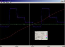
I got this graph of motion while sitting at home from a motor over the internet. Getting the speed should be easy. There are status bit that indicate when the motion controller is at constant velocity again. The plc only needs to look at the state status bits to tell when the motor is stopped, accelerating, decelerating or at a constant speed. It took me far more time get the .jpg and write this than to get the data.

I do this by using the counts each scan to calculate speed and I filter the speed using a low pass filter. This has been covered many times before.

calcspeed.jpg
 
Hi Tim,

Generate a 50khz pulse train (0.02ms timebase) with elapsed value, and read your pulses as interrupts. 180hz means 277 timebase pulses between interrupts. 500hz means 100 timebase pulses between interrupt.

You have the opportunity to decide accurately which is the currently used freq. 100 kz (or more) "timebase" freq rates would also improve the "resolution".

Advantages: the response time is not fixed but sticks to your actual tracked signal + Every pulse counts. Uncertainty: how close are two consecutive freq ranges?

In the interrupt program:
- read the elapsed timebase counter
- reset the elapsed timebase counter
- consider the current freq range and write a set of three internal data accordingly: actual freq in use (data1=1 to 4 or 5), freq changed information (bit), previously used freq (data2=1 to 4 or 5).
- actual freq number in use AND no freq change: transfer data1 to index1. Increase an indexed word by 1 (counters area)
- in case of freq change: transfer data2 to index2. Transfer the indexed value (extraction from counting area) to the sorting area.
- reset the freq change bit

The "freq changed" bit and associated processes may be managed and reset in the normal scan (no time lost in the interrupt).

Will you try?

Laurent
 
Wow

Hi guys. Alot of good information here!

To all in favor of the voltage model, I actually bought my Unitronics model with that in consideration. It's still an option. I could either pick up the command voltage from the "host PLC", or configure the servo drive to output it on a monitoring output. Still an option.

My original idea for this was to use the Uni's 2.5mS programmable interrupt as a sort of stopwatch. By counting the .0025 increments in a movement and in a timeframe, I could get an approximation of travel and velocity. I finally rejected this from concerns of accuracy, but it might be time to circle back around to it, since HSC isn't working out.

Peter:
My controller in this case is a B&R PLC, the design of which is locked up tighter than a chastity belt. The only thing I can get from this is the command voltage.

Now, the servo drives themselves are stromag, and a little more amenable. They provide an encoder passthrough, and have configurable monitoring outputs that might be of use as well.

Laurent:
There is the seed of a solution here in what you say. Perhaps as follows:

Using the 2.5mS routine of the Unitronics.

1. Sample the analog command voltages to all four drives.
2. If the voltage does not change more than, say, 10% from the previous sample, set a Voltage Stable bit.
3. Create new +/- limits around the sample for the next read.

In my main program, read the Voltage Stable bit. Each time it comes on, record the frequency of that portion of the move. When it goes off again, record the pulse count as distance travelled.

Is this close to what you described?

Thanks to everyone! This one is by no means settled.

TM
 
Last edited:

Similar Topics

I am working on a project using AB PLCs and PanelView HMIs. There is a desire to allow control loop setpoints to be provided through the HMI or...
Replies
11
Views
3,684
I've used Banner for RTD's, thermocouples and 4-20's but not for discretes. I called the factory to find out whether either PNP or NPN wiring...
Replies
1
Views
1,470
The hole size to mount a through door handle is 65mm to 70mm. I can not find a punch that will work in Stainless Steel. What are you using to...
Replies
1
Views
1,134
Hi; We have below mentioned softwares for PLCs, PVs drives etc. I want to ask what is the best practice to handle these softwares, should we...
Replies
9
Views
2,968
If you get a cold call to come out and work on a system with ControlLogix and PanelView HMI, how can you determine which major firmware revisions...
Replies
15
Views
3,819
Back
Top Bottom