Help with an edge detect

Guest

Guest
G
I am attempting to find a solution for a program that I have to put together. First off, it has been several years since I have worked with a PLC, mostly I have been using single board computers. I dont recall how to work everything out in ladder, I have been using code/line based stuff for too long I guess.

What I am doing is this:

I have a rotary indexer that I am building. It is for metering part flow through a system. The indexer looks like the chamber for a revolver. I have 3 sensors hooked to the indexer. 2 sensors for part presence (the chamber they are loaded in and the chamber they exit from) and another prox switch to tell me when to stop rotating the indexer.

What I would like to do is this:
first part loads and trips the first sensor
check to see that the discharge is clear (sensor 2)
rotate the indexer 1 chamber, stop rotating when the prox (sensor #3) trips
first part exits the chamber in position #2 and clears sensor #2 while the second part loads into the indexer.
Sensor #1 is triped by the second part. Rotate the indexer when part #1 clears sensor #2. Continue rotating the indexer until the prox trips on the next chamber.

Logically, when sensor #1 is tripped and sensor #2 is not, latch the output to the motor on until sensor #3 trips. Repeate. My problem is that sensor #3 is on any time the indexer is not moving and is still on for the first few degrees of rotation. so that logic does not quite work. The output will essentally only be on for one scan and constantly be switching on and off each scan cycle.

I am using an Allen Bradly micrologix plc with RSlogix 500. I would think this would be fine if I could just have the rung that is looking for the prox to stop the motor look for the edge of my sensor but I do not see any paticular controls for doing that.

Again, I am not that framilliar with PLCs and this is the first time I have tried using an Allen Bradly PLC. This is probably somthing super simple and I just don't know where to look for the function.

Thank you in advance for the assistance!

Cheers

Spike
 
why don't you post your logic and give us a picture of the process, that will help greatly.

After reading the OP, this is my understanding:

Inputs:

S1 - Part in sensor
S2 - Part in Exit chamber sensor
S3 - indexer prox

output:

R - Output to turn on rotation


What I think you have

S1 S2 R
----| |-----|/|------------------(L)-
this turns on the rotation

R S3 R
----| |-----| |------------------(U)-
this turns off the rotation


It don't work for you because S3 is on for the 1st few seconds. So it sounds like you need a delay before unlatching R.

So add this Timer On Delay between the two ladder

R T1
---| |------------------------TON-

and modify the unlatch rung

R S3 T1.TT R
---| |---| |---|/|-------------(U)-


gg. it's Friday

oops, I should add you probably need another timer to stop regardless of the feedback from S3 as a safety measure. This is not by any means complete
 
Last edited:
Yes, it is Friday... just with I had more days off this month other than xmas. Oh well.

Thanks for the suggestion. I'll try that out, it looks like it will work.

Spike
 
That the way it should look.
You need the One Shot Relay (OSR) to work when the sensor meet the indexer and stop the rotation, but you need not to let it impact on the next cycle.
The OSR work for one scan time of the PLC,its enough to cut the signal to stop the rotaion.

indexer.jpg
 
Spike...

The simple answer to your question is...

Rotate until you see Prox-3 go ON.

That is not to be confused with "Prox-3 IS ON". You are looking for the Prox to transition from OFF to ON.

Transition elements look something like this...

PROX-3
--|/\|-- = Prox-3 Just Went ON


PROX-3
--|\/|-- = Prox-3 Just Went OFF


If you don't have that element available to you then you can build your own...


WAS
PROX-3 PROX-3
--| |------|/|----+---(SET) WAS PROX-3
|
+---( ) PROX-3 Just ON


WAS
PROX-3 PROX-3
--|/|------| |----+---(RST) WAS PROX-3
|
+---( ) PROX-3 Just OFF


Now...

It terms of your basic design... a couple of observations and questions occurred to me...

1. You are not monitoring the part "loading"... only that it is "loaded". Does this mean that Prox-1 is located at the exit-end of the Entry Chamber? Or is Prox-1 located at the entry-end of the Entry Chamber?

2. Does Prox-2 see the part in the Exit Chamber before the part begins unloading or only "as" the part is unloading?

3. If Prox-2 only sees the part "as" it is unloading then your program might not know that there is a part in the Exit Chamber on start-up. If this is so, then you might want the start-up routine to delay rotating until the part in the Exit Chamber has had a reasonable chance to begin exiting.

If you use only three sensors then you are relying on the system running smoothly without interruption. This can certainly work, however, on start-up, or after an interruption, you'll have to add code to ensure that the Exit Chamber is, in fact, empty before rotating.

If allowed to use as many sensors as necessary, I would use five sensors. This arrangement would provide "Positive" status information. That is, it provides "static" information as well as "dynamic" information.

Prox-1 Loading Entry....<-- dynamic
Prox-2 Entry is Loaded..<-- static
Prox-3 Exit is Loaded...<-- static
Prox-4 Exit Unloading...<-- dynamic
Prox-5 Index............<-- static and dynamic

There might be a way to use the Entry Loaded sensor and/or the Exit Loaded sensor to replace the Index sensor.

Of course, adding extra code is cheaper than adding extra sensors. It all depends on budget and performance requirements.
 
Point #1) Yes, the sensor is located on the exit end of the chamber and will only be tripped when a part is fully loaded.

Point #2) Sensor 2 is located in a similar spot on the exit chamber. The sensor will be tripped while the chamber is loaded and unloading and will clear when the part clears the chamber.

Point #3) Not an issue since sensor 2 can see when the chamber is loaded and is tripped durring the unloading and only clears when the part is clear.

Thanks for the advice! I'll let you all know how it goes.

Cheers!
 
Arik,

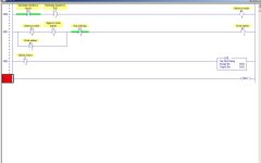
can't you make the screenshot a bit smaller?

you can call me lazy guy who doesn't like to scroll
around :)

my display is set to 1600x1200 and the thing still
doesn't fit in. it must be real ugly on screens that
use lower resolution. the simplest way is to adjust
window size before cropping so the rungs are not
that wide. cropping can also remove the huge blank
space below last rung.

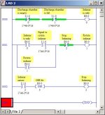
here is an example that would probaly please even
guys with oldest laptops running 800x600:

crop.jpg
 
ArikBY said:

Somehow I could not fit the rss file to my paint board.
If I may: I think what panic is referring to is dragging one edge of the ladder window closer to the other. This will narrow the width to a more compact view - taken far enough the rungs will 'break' and you'll have those funny arrow thingies (technical term) for continuation.
 
more questions

Ok, being somewhat new to PLCs, I need a little help with the addressing for this.

On Panic Mode's diagram, on rung 0001, why would you use B3:0/1 insted of O:1/0?

Next question: What is the difference between using B3 as an output vs. O?

Next question: On rung 0002 concerning the OSR bit, if my sensor is floating high and pulls low when engaged, can I reverse that function somehow to make a one shot falling vs. the one shot rising?

Thanks in advance!

Spike
 
Re: more questions

Spikedmead said:
On Panic Mode's diagram, on rung 0001, why would you use B3:0/1 insted of O:1/0?

Next question: What is the difference between using B3 as an output vs. O?

These two questions are related. Basically, you should only use O: addresses if you are actually energizing an output. Otherwise, you should use an internal bit (B3/xx, N7:xx/yy) for all of your other housekeeping needs.

Logically, there is no difference. All that the -( )- does is to write a '0' or a '1' to some memory location.

The only differnce between a "O:" memory location and a "B3:" memory location is that once programming scan is done, the real-world devices will get updated with the information in the "O:" memory locations.

You also have many fewer "O:"s than you do "B3"s (you can make more B3's to fit your need - you only have as many O:s as you have outputs.

And while TODAY there might not be anything wired to that point, you can't be sure about what TOMORROW will bring. Someone may wire something to it before checking the program. Or someone might think that you don't have any spare output points available, when in fact you do.


Next question: On rung 0002 concerning the OSR bit, if my sensor is floating high and pulls low when engaged, can I reverse that function somehow to make a one shot falling vs. the one shot rising?

There's two ways you can do what you are asking:

One, as you suggest, is to use a One-shot falling to capture the event's edge. The problem is that, in a SLC at least, a OSF is not as clean of instruction as an ONS.

Another way of doing it, is simply to reverse the logic on the sensor, like so


Indexer Sensor STOP INDEXING
I:1/2 B3:0/3 B3:0/2
-------|/|------------[ONS]-------------------------( )


What you are doing is catching the rising edge of a falling signal, which is the same as catching the falling edge of a rising signal.
 
because it is internal memory and not the output.
you could use an output as well but that's waste...
every plc has much more internal memory than outputs
and internal memory bit is cheaper than I/O point.

you can use OSF instruction instead or OSR but you
can also change trigger in front of the OSR to NC.
 
Ok, here is what I have:

indexer.jpg


For some reason, the OSF function is greyed out and I am unable to insert it into the program???

For now I just left the sensor normally open with an OSR so it will stop on the back edge of the sensor.

Question regarding the inputs. to use inputs 0, 1, and 2, I need to address them I:0/0, I:0/1, and I:0/2 correct?

Initally I had I:0/0, I:1/0, and I:2/0. RSlogix did not seem to like that though.
 
ML 1000 is not support OSF ML1200 do.
You dont need OSF the OSR is the right function for you.
When the target meet the sensor the signal raise for one scan time and stop the indexer.
The sensor might stay on the target but you can resume youe sycle even so until the signal raise again.
The inputs should be I0/1 I0/2 ....ect
Input I1/0 belong to the next Input regester something you havnt.
 
I see. That would explain why a lot of the functions on the palate are unusable. I figured that was what was up with the inputs as well. I kept getting "un-configured I/O" errors.

That all should do it! Thanks for the help everyone. If I have any more questions, I know where to go for answers!

Cheers!
 

Similar Topics

Title summarizes the overview of the problem. I am trying to make AVEVA Edge 2020 and a Schneider TM241CE40R to talk to each other via Modbus...
Replies
18
Views
2,047
Hi all forum members, i need the full text of item 1074125. i don't have a tech connect account. i have some issues when connect to ml1400 with...
Replies
7
Views
1,698
This is a simple program, but since I'm always trying to improve; I thought I would ask here. I want to know if there is a better way of...
Replies
0
Views
1,353
Hi My Name is Jason Woods and I work in HR at Honeywell. I have multiple positions that we are seeking knowledgeable individuals that have...
Replies
0
Views
2,366
Dear all, I am looking for some websites / books which will give me good understanding of the control strategies implemented in process...
Replies
1
Views
1,579
Back
Top Bottom