SLC 5/05 and 1336 Plus

subjwd

Member
Join Date
Oct 2004
Posts
18
I am in need of assistance. I have been programming PLC's and working with VFD's for a few years now, but I have been given a project for which I have no references.

I am using a SLC 505 and (2) 1336 PLUS's. Per the specs, the PLC is to be set up as rack 1 and the (2) 1336's must be set up as remote rack's 2 and 3.

My question is what communications are they referring to here? Is this a Remote I/O configuration or is it something that is setup via Ethernet, or simply straight field wiring?

Generally, I have controlled VFD's using a straight 4-20mA signal, run enable and running/speed feedback.

How would you interpret this? Thanks for your help.

JD
 
It sounds to me like your customer is specifying the use of Allen-Bradley Remote I/O protocol (RIO, which was a standard part of PLC-5's).

You install a 1747-SN scanner module in the SLC-5/05 chassis, and run the twinaxial cable in a daisy-chain to the drives, which will be equipped with a 1203-GD1 or 1336-GM1 adapter.

The 1203-GD1 is an external adapter, and the 1336-GM1 is onboard the drive.

Usually the remote I/O Adapters are given "rack" numbers starting at zero in this setup. You could make one drive "Rack 0" and the other "Rack 1".

There is a lot of information about the drive interfaces at http://www.ab.com/drives
 
OK, I need a little further help then. I haven't done much Remote I/O work. Can you point me to a reference of how to set up these drives as Remote I/O to a SLC 5/05?

As I said, I always did 4-20mA signals before, without ever "assigning" VFD's. Can you point me to a reference that tells me how to set this up and how to program it, as in something that shows examples?

Again, thank you for the help.

JD
 
It's been awhile since I did this, and my memory isn't what it used to be, so my information may not be correct. I'm doing this from home and don't have all my usual "resources" with me.

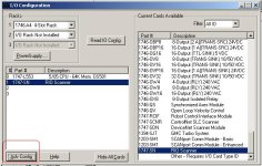
Select the 1747-SN in the I/O configuration section of RsLogix500, then click on the Adv Config button at the lower left. This will bring up the "advanced I/O configuration" config screen. Then click on the Edit G data button at the lower right. This will bring up the screen where you set up your racks, groups etc....

The drive manual will tell you how to set up the drive addresses, rack, group etc... If I remember correctly the 1336 is a 1/4 rack. So you'll have two words for each drive. One word is an output word and is used to send the "speed" to the drive, the other word is a status word and different bits indicate the status of the drive, there is an at speed bit, fault bit etc...

I have used this arrangement a lot and once you get used to it, I think it's much easier than the hardwired method. There's no scaling involved, and you get all the status bits, without pulling all the extra wires. One "blue hose" is all that required to connect many devices. I also use it for 3rd party devices, such as weigh scales.

Here's a link to the AB knowledge base, do a search for what you need and there may be some helpful articles: http://domino.automation.rockwell.com/applications/kb/RAKB.nsf/$$Search/?OpenForm

ioconfig.jpg
 
Last edited:
Greetings JD,

besides all of the excellent advice from my distinguished colleagues Ken and Ken, you might want to take a look at the:

Remote I/O Scanner (1747-SN) User Manual

you’ll probably need to read most of it before you’re through but page C1 [Adobe Reader page 178 of 188] would be a good place to start ... this is a “road map” chart of how the various “racks” are laid out in the SN module’s addressing scheme ... things will be easier to understand if you make a Xerox copy of this page and pencil in your address assignments as you go ...

and just a tip ... regarding this part of your first post:
Per the specs, the PLC is to be set up as rack 1 and the (2) 1336's must be set up as remote rack's 2 and 3.
this specification doesn’t make a lot of sense ... the SLC won’t be set up as a “rack” in this type of system ... my guess is that the guy who wrote your “specs” was a lot more familiar with the larger PLC-5 family than with the SLC system that you’re working on ... the specification that you mentioned would come a lot closer to making sense with a PLC-5 system ... you might want to check into this issue before you finally start to nail things down ... as a point of discussion, the "rack 0" and "rack 1" assignments that Ken Roach suggested would be much more typical in the system you're setting up ...
 
and one other thing ... have you considered how the system should react if (when) someone kicks the “blue hose” cable loose someday? ... like Ken Moore said, the “remote I/O” method is a handy way to let your SLC control the drives ... but you still need to plan for the inevitable “can’t communicate” scenarios ...
 
The problem I was presented was originally written for PLC-5's. The basic layout was to have a PLC-5 (rack 1) with (2) 1336+ VFD's (racks 2&3) for one process, and another PLC-5 separate (rack 0) for another process. The results of the second process are an input for the first process. Basically I read a fluid level in the second process, and I control the first processes pumps and valves based on that level.

All of them communicated via RIO.

I do not have the software for PLC-5's, so I am doing it as if it were using SLC-5/05's. I am trying to figure out how to setup and configure the racks for this. Do I put a 1747SN in each PLC rack or does one of them need a 1747ASB card?

Basically, I need a guide of how to set up these racks and what configuration/ladder logic I need to write to make the PLC's talk.

JD
 
Greetings JD,

you said:
The problem I was presented was originally written for PLC-5's.

bingo! ... I thought so ... now the spec makes more sense ...

I do not have the software for PLC-5's, so I am doing it as if it were using SLC-5/05's.

no offense intended, but that’s not a good plan ... you’ll be ok from the drives’ standpoint ... but there are MAJOR differences between how the PLC and the SLC platforms handle their remote I/O addressing ... basic idea: you’re probably going to waste more time than you’re going to save by this particular “temporary workaround” ...

Do I put a 1747SN in each PLC rack or does one of them need a 1747ASB card?

(note that some of this can change depending on how the existing system is configured) ... for the PLC-5 you won’t need an SN-type module at all ... each PLC-5 processor will have a built-in channel (channel 1B) to handle its remote I/O link ... on the other hand, the SLC system WILL need an SN module since there is no built-in remote I/O link on the processor ...

The basic layout was to have a PLC-5 (rack 1) with (2) 1336+ VFD's (racks 2&3) for one process, and another PLC-5 separate (rack 0) for another process.

no offense intended but this doesn’t make much sense ... each PLC-5 system will have its own “Rack 0” ... and its own “Rack 1” ... and its own “Rack 2” ... and its own “Rack 3” ... and it may have even more “racks” depending on the size of the processor ... what size are you working with? ... examples: PLC-5/20; PLC-5/40; PLC-5/80, etc. ... the “racks” I’m talking about are built into the processor ... secret handshake: the definition you need to be working with is:

a “rack” equals 8 words of input AND 8 words of output ... and incidentally, there are 16 bits in each word

... in other words, the term “rack” is a measure of hardware size ... it’s something like a “dozen” eggs ... or an “acre” of land ... specifically, it is NOT a number used to identify a “chassis” hanging on the wall ... confusing this issue is a VERY common mistake when you’re first getting started with this stuff ... if you need more help with this concept, then post again and ask specific questions ... this is a BIG topic ...

Basically, I need a guide of how to set up these racks and what configuration/ladder logic I need to write to make the PLC's talk.

plan of attack: tell us EXACTLY what type of PLC-5 system you’re going to be using ... and what flavor of addressing each one is going to be set up for ... examples: two-slot; one-slot; or half-slot ... and it would be a VERY GOOD idea to post the existing .RSP program files for each existing PLC-5 system ... we can get started from there ...

but in the friendly advice department: scrap the “temporary SLC workaround” idea ... setting that up is going to be quite labor intensive ... and then you’re going to basically have to start all over again (almost) from scratch in order to make the system work for the PLC-5 platform ...

better plan of attack: involve your local Allen-Bradley distributor in this project ... the sooner the better ... they have people on staff to help you set this up ... since you’ll be buying the hardware and software from them anyway, they should be available to help you get the system laid out ... this is what distributors do ... (now THERE’S an invitation for a rant or two) ...
 
Last edited:
Ron,

This project I have been given is an exercise in programming, not an actual physical application.

It was designed that there are two PLC-5's, one for blending and one for filling operations. Per the problem statement, here is what I have been given:

Blending PLC (1785-L80E)
- various transmitters, switches, etc. wired to I/O modules in rack 1
- 1336+ communicating to PLC as remote rack 2
- 1336+ communicating to PLC as remote rack 3

Filling PLC (1785-40E)
- various transmitters and sensors wired to I/O modules in rack 0

Blender PLC needs to know an analog value from the Filling PLC in order to control the 2 VFD's and some valves.


My issue is I only have RSLogix 500 software. I suppose I can write the logic out by hand instead of using the software, but it seems like it would take a lot longer. So, I was trying to convert this problem over to SLC5/05 logic instead. I have no PLC5 books or anything, only SLC.

This is a minor part of the exercise I have been presented. The majority of the exercise is writing the rest of the ladder logic for the 2 PLC's to control the two systems.

I basically need some assistance on setting up the intercommunication between the PLC's and the drives.

JD
 
foreword: I wrote the stuff below before I read your latest post ... I'll read that now ... some of what I've written might change but this will help get us started ... also: if you want to, you can send me a Private Message with your phone number ... I'll give you a call and try to talk you through some of this ... this typing is killing me ... I'll be here for about 30 more minutes then offline for the weekend ... sorry but my boss won't let me send you my number ... the last time I gave that out, the guy posted it as part of his "thank you" and I got way too many "help me" calls from people I'd never heard of ...

and so:

and here’s a little screen shot that might help make the PLC-5’s addressing scheme a little more understandable ...

[attachment]

in this “decimal” display mode, each colored horizontal bar is one-half of a “rack” – specifically 8 words on the input table ... don’t forget the “output” side of the “rack” definition ... the first two digits in each word’s address indicate the “rack” number ... example: in “I:000” or “I:001” the digits “00” indicate that these words are located in rack 00 ... in “I:024” or “I:026” the digits “02” indicate that these words are located in rack 02 ...

note that this is an example of a PLC-5/20 processor ... a larger type processor (example: PLC-5/80) would have many more racks of I/O on this chart ...

in the PLC-5 system, “rack 00” is always reserved for “Local I/O” ... specifically, I/O which resides in the same chassis with the processor ... you cannot assign either one of your drives to this particular rack because they are not LOCAL I/O – they are REMOTE I/O ...

going further ... you MIGHT be able to assign your drives to “rack 01” and/or to “rack 02” ... but then again you might not ... depending on how your local addressing is set up (two-slot, one-slot, or half-slot) and on how large the local chassis is (example: 8-slots, 16-slots, etc.), then the rack assignments for “rack 01” and/or “rack 02” might also already be taken up for local I/O ... that’s why I recommend that you post your .RSP program files ... we can usually tell enough from those to figure out what assignments are - and are not – available ...

sanity check: I’ve already mentioned that this is quite a big subject ... we can help you through it but it’s not going to be as “quick and easy” as you might hope ... some people complain that the Allen-Bradley addressing scheme is the most complicated and convoluted system in existence ... I won’t argue that point one way or the other ... but other people point out how incredibly flexible it is ... and I won’t argue that point either ... regardless of how well you do - or do not – like the system, these are some of the issues involved ... like they say: “if it was easy, everybody could do it” ...

so how about calling in your local distributor? ... how’s that idea starting to sound? ...

plan of attack: post the information I asked for and we’ll get started ... by the way, what’s your deadline on this project? ... note that “as soon as possible” is not a valid answer ...
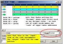
racks plc5.jpg
 
This project I have been given is an exercise in programming, not an actual physical application.

is this a student assignment - for a grade? ... or a “boss man’s” assignment to keep you occupied? ... or something else? ... we’ll still try to help, but the more we know about the project, the easier things get ...

It was designed that there are two PLC-5's, one for blending and one for filling operations. Per the problem statement, here is what I have been given:

Blending PLC (1785-L80E)
- various transmitters, switches, etc. wired to I/O modules in rack 1

that last statement ("in rack 1") is giving me heartburn ... it COULD be done, but it just sounds “fishy” ...

- 1336+ communicating to PLC as remote rack 2
- 1336+ communicating to PLC as remote rack 3

as long as those rack assignments are available, then this is no problem ...

Filling PLC (1785-40E)
- various transmitters and sensors wired to I/O modules in rack 0

no problem here ...

Blender PLC needs to know an analog value from the Filling PLC in order to control the 2 VFD's and some valves.

maybe your “assignment taskmaster” wants you to make use of a “message command” over DH+ (Data Highway Plus) ... could that be part of the puzzle? ... this would be a natural way for the two PLCs to communicate ... has the term DH+ come up before? ... there is another “far out” possibility ... the PLC-5 processor can be set up to operate in the “adapter mode” ... in other words, it basically operates as a remote I/O rack of another “master” PLC-5 processor – in addition to controlling its own local I/O ... this can be done – but we’re getting way out there on the bleeding edge of things with this idea ... it might be part of your “assignment” but it is NOT commonly done in the field ... do you think that this is what your “taskmaster” had in mind? ...

My issue is I only have RSLogix 500 software. I suppose I can write the logic out by hand instead of using the software, but it seems like it would take a lot longer. So, I was trying to convert this problem over to SLC5/05 logic instead.

if there is not – and NEVER WILL BE – any physical hardware involved, then will you still be able to meet the requirements of the assignment by using an SLC platform for your solution? ... if so, then we can work from there ...

I have no PLC5 books or anything, only SLC.

the PLC-5 books are readily available on the internet ... we can show you where to look ...

This is a minor part of the exercise I have been presented. The majority of the exercise is writing the rest of the ladder logic for the 2 PLC's to control the two systems.

reality check: this ain’t going to be what I’d call “minor” ... as for the ladder logic, once the addressing assignments have been made, then it’s usually a matter of programming in something like an MOV (Move) instruction to change the drive’s speed ... ROUGH example: MOVing 32000 to O:010 might make the drive go to full speed ... MOVing 16000 to O:010 might make the drive go to half speed ...

I basically need some assistance on setting up the intercommunication between the PLC's and the drives.

and to get that assistance we need to know more about the system ... like Babe Ruth said: “you can’t hit ‘em if you can’t see ‘em” ...

finally ... it looks like you're still online as I'm posting this ... if you're going to PM that phone number, then it had better be quick ... my wife has things for me to do this afternoon ...

and in case you’re skittish about sending someone on the forum your phone number, here are a couple of past “references” ...

http://www.plctalk.net/qanda/showthread.php?postid=55447#post55447
http://www.plctalk.net/qanda/showthread.php?postid=71592#post71592
 
Last edited:

Similar Topics

I’m attempting to send a temperature from a SLC-5/02 to an EZiMarquee display. The vendor said to use a MSG instruction to send the data to the...
Replies
1
Views
81
Hello all. I have a few SLCs in my plant and of late we've seen a weird issue: The system will be running normally and then randomly the outputs...
Replies
2
Views
92
I am working on setting up a Prosoft Datalogger model PLX51-DLplus-232. This unit will be collecting data from a SLC 5/05 on the DB9 port set to...
Replies
3
Views
99
I have a redundant ControlLogix being set up. This program reads a value from a remote site which happens to be SLC PLC. Rockwell mentions SLC...
Replies
2
Views
94
Hello, I have a ControlLogix redundant controller being set up. The program reads a value from a remote site which hosts a SLC PLC. Rockwell...
Replies
0
Views
76
Back
Top Bottom