Easy Maths?

ben

Member
Join Date
Jun 2002
Posts
37
Hi All,

I have come across a signal convertor unit, that converts a voltage to another. I did some checks on this with my dvm and came up with the following readings:

D.C. Signal In

7.5
7
6.5
6
5.5
5

D.C. Signal out

13.29
11.41
8.89
6.42
3.97
1.457

Tonnes In

37.5
35
32.5
30
27.5
25

Now I need Tonnes Out?

I can't seem to get my head around the maths on this one? However I think this unit has been used to increase the scale over a range of weight (25 to 37t) to give more accuracy, in this range. After this unit the input goes directly to a PLC input.
What I would like to do is convert the existing weigh signal, 0 to 50t to operate over this range. Using the mA loop between 25 and 37t as described above. However this is not a simple ratio matter, as you know with different slopes on each signal, the ratio varies over time/emptying and is not fixed.
Please help if you can offer anything?

Thanks as you say here (in advance).

Ben
 
By looking at your numbers, it appears that this may not be voltage converter. It may be a signal isolator from 4-20mA input to either voltage or current output.
You may want to check the I in and out.
 
I'm not exactly sure what you want as your result. So I'll just make some general observations.

The data set you list as 'DC Signal In' already maps to the data set 'Tonnes In' as:
0-10VDc = 0-50tonnes

So if you just want to have the input range be 0-50 tonnes you simply take your raw DC signal in volts and multiply it by 5 to get tonnes.

You can generically scale any linear signal to any linear user unit using the basic equation for a line:

Y = mx + b
Where:
Y => scaled user unit
m => line slope (change in Y divided by change in x)
x => input data
b => line offset

In the base example of 0-10VDC = 0-50tonnes:
m => 5 ((50 - 0) / (10 - 0))
b => 0 (user units go through zero as data in goes through zero)

You can figure out your own m and b for any matched Y and x data set you choose IF YOU KNOW THE RELATIONSHIP IS LINEAR just by m,anipulating the above equation.

Weighing applications are generally linear assuming you are using the weight signal to determine product weight and not product height or something like that. So, while you may have an offset to worry about, there should only be one slope.

I hope this helps.
Keith
 
Maths problem

To explain a little more,

I am sure the input is V and not I.

The first input to the card is 0-10vdc from the weigher amp. There is PD (Potential divider) that drops the voltage from 10vdc to 5vdc that the input card can handle. This displays the normal weight in the program.

This same 0-10v signal from the weigher amp, is taken to the convertor unit described and only operates over the range 5v to 7.5v giving the outputs described in the previous post. eg, it only switches on the output at 5v to a max of 7.5v. This ouput signal only goes to the max of 13.29vdc. This altered signal then goes to a similar PD as described above and into the card as weight 2.
This signal (weight 2) is then used to calculate the flow. When I use the first weight in the new program, the calcualtion does not work. Hence the post for some help.
I can only assume that this unit gives a greater rate of change to increase accuracy? Q. Am I being to fussy here and its time to write some new code? Rather than using the existing calcs, and trying to convert my weigh signal 1 into the new weigh signal 2.

I would like to add that this equipment is 20+ years old, and maybe this is something to do with the fact that weigh signal 1, over a range of 0-5v would offer no accuracy when scaled 0-50T over the range of the check weigh. (37.5 to 25t) So the designer increased this scale so the weigh calculation would be more accurate?

I like a challenge, and this seems to be one, and its the usual case of this needs to be running yesterday, sort of job.

Ben
 
Even 20 years ago 0.1% accuracy was no problem. It would help if you could tell us exactly what equipment/PLC you're using here. Perhaps there is an easier solution than maths.
 
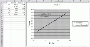
Using trusty ole' Excel, here is your plot and equation. I assume that you want to take the DC Out and convert it to Tonnes in the PLC. If so, use the equation :

y = 1.0405x + 23.37

That should do it.

tonnes.gif
 
Eating Breakfast

All,

You have been most helpful, I too plotted the graph.
I think what I need is a graph for the dc in vs dc out.

I can then convert the weight 1 to weight 2 using this equation.

I don't think I am quite there yet.

Ben
 
Alphageek, how do you do that in Exell?
I've did a quick search on Google but don't know what keyword to search for to get a good tutorial...
 
Click on the chart, got to Chart Menu, Add Trendline, Options, click Display equation on chart.

You can also use the Linest function, but it is non-intuitive and takes some playing with the first time you use it. There is an example in the Excel help topics.
 
Last edited:

Similar Topics

See picture. I want to add a rung (magenta) into the existing code. Can't figure out how to do this. I select a -||- , right? When I drag/drop...
Replies
21
Views
1,787
Hi All, On my site, the standard template for storing recipes in the PLC is to create a tag called PartRecipe which is an 2D array - for example...
Replies
4
Views
1,468
I would like to do change a kinetix drive, so i believe i just have to put the IP address in the new kinetix and just connect right? Do I need to...
Replies
1
Views
1,196
Hey all, I am trying to check in logix designer in emulator and I need to check the hmi alarms by toggling bits to activate an alarm . But...
Replies
4
Views
2,066
Good afternoon guys, I have a basic question on the bubble level in the picture attached. This is probably really easy, but I don't get it, haha...
Replies
11
Views
3,344
Back
Top Bottom