AB OTL OTU Question

Grover

Member
Join Date
Oct 2002
Location
Bay Area, California
Posts
22
Greetings.

I am new to PLCs and this is my second post. I am researching an intermittent condition where the motor starts unexpectedly, which is obviously undesirable. We are using an AB SLC5-05. The VFD motor is controlled by a relay energized by O:14/9. This address is set (1) only once at rung 0026 and reset (0) once at address 0028 throughout the entire program.

I don't understand why the programmer put the XIC O:14/9 instruction in parallel with the timer done XIC 0026. Once the timer is done, the motor relay closes and should stay that way until rung 0028 goes true, right? Not shown is the previous rung for timer T4:15 which stays false.

A respected engineer in my group (respected = he knows more than I do) thought that if the rung for the OTL remains true, a subsequent OTU cannot effectively unlatch it. This doesn't seem right to me.

Any thoughts?

Grover


3-SEC ALL MOTOR
START INTLKS RELAY
DELAY CLOSED CLOSED
T4:15 B3:2 O:14
0026 ------] [--------] [----------[L]-------
| DN | 14 9
| |
| O:14 |
---] [---
9

STOP MOTOR MOTOR
MOTOR WINDOW RELAY
LATCH GOOD OPEN
B3:3 B3:2 O:14
0028 ------] [--------] [-----------------
10 6 9


 
It's hard to say without seeing the rest of the program, but with Set and Rest logic it is entirely possible to have the conditions that set B3:2/14 true even if the conditions that set B3:2/6 are false.

This kind of thing is tough to de-bug on the fly, one of the reasons I absolutely avoid Set and Reset if at all possible. Instead, use a latching circuit to a standard coil.


START INTLKS RELAY
DELAY CLOSED LATCH GOOD CLOSED
T4:15 B3:2 B3:3 B3:2 O:14
-+----] [--+-----] [------]\[----]\[-----( )---
| DN | 14 10 6 9
| |
| O:14 |
+---] [---+
9


Now you can see what is going on, and not just the status of O:14/9 at the end of the scan.
 
I am researching an intermittent condition where the motor starts unexpectedly, which is obviously undesirable.

I am going to address this differently, the way you stated the problem says the machine is going from a stopped position to start by itself. It is possible you have code issues if this is a new machine, if its been around awhile and this problem just started then another approach needs to be taken.

First and foremost I would look at the device and wiring that is used to start the machine. This could be an intermittent short, bad button etc. The drive itself could have a problem.

Look at the code online if possible, see if the timer done bit goes false after it starts, if it doesnt and b3:2\14 stays true and either B3:2/6 or B3:2/10 are false then the system could start.
 
Grover said:
A respected engineer in my group (respected = he knows more than I do) thought that if the rung for the OTL remains true, a subsequent OTU cannot effectively unlatch it. This doesn't seem right to me.


The last state of the output is what is written to the data table. Thus if the unlatch rung is true, the real-world output would be off. It is effectively be unlatched.

The branch in the first rung does seem redundant.

Tom's rung is less confusing and easier to troubleshoot. Unfortunately, I don't see how the device can start w/o your timer finishing.
 
Grover said:
I don't understand why the programmer put the XIC O:14/9 instruction in parallel with the timer done XIC 0026. Once the timer is done, the motor relay closes and should stay that way until rung 0028 goes true, right?
Right, the XIC O:14/9 in parallel serves absolutely no purpose, but it will not affect the operation of the rung. It's probably a leftover from the programmer's original design before he decided to use a latch.
Not shown is the previous rung for timer T4:15 which stays false
This is NOT true... Timer T4:15 HAS TO time out in order for the O:14/9 latch to occur (based on your statement that O:14/9 is no where else in the program. Actually, you said the these rungs are the only place where O:14/9 is set and reset. Does this mean there might be an OTE O:14/9 somewhere? IOW, is there any other place where the state of O:14/9 gets modified? (like via an HMI?). This is the ONLY way O:14/9 could get turned on.
A respected engineer in my group (respected = he knows more than I do) thought that if the rung for the OTL remains true, a subsequent OTU cannot effectively unlatch it. This doesn't seem right to me
Most likely you're right... Scanwise, the state of O:14/9 at the end of the scan will be what gets written to the physical outputs (Unless there is an "immediate update" done mid-scan)...

Enough of the explanations... Assuming nothing else if affecting O:14/9 elsewhere in the program, replace your 2 rungs with Tom's non-latching version. This will be much easier to troubleshoot, but realize that this is simply duplicating what you already have, so don't expect it to "fix" your intermittent condition.

beerchug

-Eric
 
Let's see, two replies have focused on B3:2/14 and B3:2/6, both of which I included only to add background and methinks I've added clutter. Both of those conditions aren't suspect under normal operating conditions. B3:2/14 are service panel doors and B3:2/6 ensures the motor stops at one of four predetermined positions.
True or false, they should not cause a phantom start.

I know this is hard for you guys because time doesn't permit me to elaborate or create the ladder diagrams quickly enough. I've added rung 0024 to show how the T4:4 timer works.

The code is not new and no hardware changes have occurred that I am aware of. The suggestion about hardware being the problem is a good one. The start pushbutton I:6/0 is not suspect because the start alarm doesn't sound, the motor just starts. A bad drive wasn't considered and I will have to look into that one.

Connecting online is something else I will have to look into. Timer T4:4 should reset and that is an area to focus on.

Tom, if I understand your last suggestion, your idea is to latch the relay closed external to the PLC (O:14/9) and not rely on the PLC to hold it closed. Is this correct?


START MAIN START
MOTOR MOTOR DELAY
BUTTON OFF ---TON--
I:6 O:14 | T4:4 |
0024 ------] [--------]/[-------| 0.01|-----
| 0 | 9 | | 300<| |
| | | | 0<| |
| T4:4 | | --------- |
---] [--- | |
TT | START ALARM |
| O:15 |
-----] [--------
2

3-SEC ALL MOTOR
START INTLKS RELAY
DELAY CLOSED CLOSED
T4:15 B3:2 O:14
0026 ------] [--------] [----------[L]-------
| DN | 14 9
| |
| O:14 |
---] [---
9

STOP MOTOR MOTOR
MOTOR WINDOW RELAY
LATCH GOOD OPEN
B3:3 B3:2 O:14
0028 ------] [--------] [-----------------
10 6 9
2

 
Rung 24 shows TON T4:4, rung 26 shows XIC T4:15/DN... These are different timers... Typo? If not, start looking for T4:15...

Also:

"True or false, they should not cause a phantom start"

True

beerchug

-Eric
 
Tom:

The functional equivalent of the Latch/Unlatch logic is not what you drew, but the following


START INTLKS STOP RELAY
DELAY CLOSED LATCH CLOSED
T4:15 B3:2 B3:3 O:14
-+----] [--+-----] [---+---]\[---+-----( )---
| DN | 14 | 10 | 9
| | | |
| RELAY | | GOOD |
| O:14 | | B3:2 |
+---] [---+ +---|/|---+
9 6


That is, BOTH Stop Motor Latch and Motor Window Good must be ON for the seal to break.

Grover:
As others have said, your Guru is wrong. If the conditions are true to do the Unlatch, then the next scan, the Output bit will be Off coming into the latch rung, and thus the branch with the output contact won't be the cause for the Latch to make. As Rick pointed out, that branch is useless.

The biggest problem that I see, at a glance, with the second logic that you posted is that, while not having your interlocks prevents you from STARTing the motor, loosing the interlocks does NOT shut it down. That sounds bad, but without knowning more, it's impossible to tell.
 
Last edited:
Eric,

Oops, good catch. T4:4 and T4:15 are one and the same. I've updated the diagram. As for interlocks not stopping the motor, they, and a myriad of other inputs are connected in parallel to the motor stop latch on rung 0028. (You guys have a tough job trying to decipher problems with the little info your given.) I wanted to give just enough information to get my point across about the OTL/OTU. By the way, there are no OTE instructions for O:14/9, just the OTL and OTU given at 0026 and 0028.

My question about OTU/OTL has been quite satisfactorily answered. As I expected additional insight and advice were offered and most appreciated.

Thanks again, guys.

Grover

__________________
:c{ )


START MAIN START
MOTOR MOTOR DELAY
BUTTON OFF ---TON--
I:6 O:14 | T4:4 |
0024 ------] [--------]/[-------| 0.01|-----
| 0 | 9 | | 300<| |
| | | | 0<| |
| T4:4 | | --------- |
---] [--- | |
TT | START ALARM |
| O:15 |
-----] [--------
2

3-SEC ALL MOTOR
START INTLKS RELAY
DELAY CLOSED CLOSED
T4:4 B3:2 O:14
0026 ------] [--------] [----------[L]-------
| DN | 14 9
| |
| O:14 |
---] [---
9

STOP MOTOR MOTOR
MOTOR WINDOW RELAY
LATCH GOOD OPEN
B3:3 B3:2 O:14
0028 ------] [--------] [-----------------
10 6 9


The code is not new and no hardware changes have occurred that I am aware of. The suggestion about hardware being the problem is a good one. The start pushbutton I:6/0 is not suspect because the start alarm doesn't sound, the motor just starts. A bad drive wasn't considered and I will have to look into that one.

At this point it doesnt matter about the code, its been working and doesnt look to be able latch on its own BUT you need to verify that the Output O:14/9 is not ON when it starts on its own...if it is ON then there are 2 possibilities,
1. The code is latching the output for some obscure reason...as most have stated this is the least likely suspect.
2. The output itself is bad....nothing unusual about that. This can be tricky because I have seen bad cards turn the output on with LED but be OFF in the program, thats why the need to monitor online.

If O:14/9 is NOT ON when drive starts itself then you know you have either
1. Wire shorting to give run command to drive
2. Drive internal problems

Naturally there could be other reasons that I havent thought of at this point but hopefully this will help you in looking.
 
Yo, Grover,

These guys are giving you excellent advice on troubleshooting your “phantom startup” problem. But you did bring up some valid questions about latches. And along those lines, there’s one thing that hasn’t been mentioned in the discussion of latches/unlatches vs. seal-in rungs. Since it concerns common misunderstandings which are safety related, I’m going to add my $0.02 worth.

The book says that latches are “retentive” - meaning that they will “retain” their ON status when the processor is changed from the Program to the Run mode - or if the power to the processor is cycled off and then on. Here is what that means in actual practice.
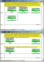
[attachment]
So when the plant’s power comes back on, the sealed-in SAW stays off - but the latched-on GRINDER starts running again. And woe to the operator who foolishly reached inside the grinder while the power was off.

Now based on this screen shot, some guys might think: “Well, I just won’t ever use a Latch. I’ll always use a seal-in just to be on the safe side”. But consider this. Suppose that an automated lumber mill uses a PLC to track where the logs are located as they move through different sections of the mill. Suppose that the programmer used “seal-in” rungs to “remember” that there’s a log in Section A, but Section B is empty, etc., etc. Now the power to the plant flickers. Where are the logs? The PLC just “unsealed” all of its memory bits. It now thinks that ALL of the sections are empty - and uses a hydraulic ram to shove a log into a section which is already occupied. This is not a pretty picture for the equipment located in said section. Latched rungs would help take care of this problem. So latches do have their place - but we need to be careful with how and where we use them.

And good luck with your original "startup" problem.

seal vs latch.jpg
 
Last edited:
Allen, you are correct - that will teach me to be in a hurry!

Grover, you asked:
"Tom, if I understand your last suggestion, your idea is to latch the relay closed external to the PLC (O:14/9) and not rely on the PLC to hold it closed. Is this correct? "

Not exactly - I am suggesting that you use the PLC to latch the output, using an internal bit that corresponds to your output status.
 
Ron,

Thank you for that explanation of the retentive feature of a plc. I think that some programmers don't consider what happens if something fails. I'm just learning and appreciate your comments. The program I’m attempting to fix uses RTD’s to monitor bearing and winding temperatures to trip the machine if the temperature gets too high. The programmer configured the RTD channels to go to 0 deg C if the RTD fails. No alarm, no protection, no clue just a cool running machine.

Andy
 

Similar Topics

I am a beginner at RSLogix 5000 and in ladder logic in general. I am tasked with making sense of an existing program and reprogramming it to make...
Replies
8
Views
6,029
Why is it that I can use multiple instances of an otl for a bit.... and the code works just as I planned it, yet... I can't use multiple instances...
Replies
8
Views
5,011
Have a noob question regarding OTL/OTU bits. Can someone look at the attached photo and tell me why both the OTL/OTU bits are true? Then they both...
Replies
8
Views
1,951
Good morning all, I'll preface this by saying I've been an electrical tech for about 10 years, but just started doing programming in the last two...
Replies
13
Views
2,809
I have Control Logix 5000, rel16: Is it ok to have one output latch and several output unlatches for the same address in multiple routines in a...
Replies
43
Views
8,659
Back
Top Bottom