S7 - DP Addressing

RMA

Member
Join Date
Sep 2004
Location
North of Hamburg, Germany
Posts
2,052
Somewhere along the line either somebody told me, or I read somewhere, that it was better to spread DP-addresses out, rather than using adjacent addresses. I didn't understand this at the time, because I reckon either the address matches or it doesn't. However, having been told to it that way, I did and have carried this over into my current project.

After having tried detecting missing DP-Stations using SFC12 and discovering it wasn't suitable (it only registers missing DP-Stations after a 1 min Timeout - 1 min would be OK, 20 + mins is NOT!), I decided to try FC125 as mentioned in another Thread here.

This works fine and fast, but I could make my life REALLY comfortable if I were to readdress my DP-Stations so that DP-address = Module number. What FC125 returns in four DWORDS is the Bit representing the address of each faulty/missing DP-Station. So if I renumber my Module DPs 1 - 21 (plus a couple more for general switching gear) and push the CPU up to, say, 25, I could simply do:

L DW#16#34444E //Get Mask for Modules 1 - 21
L DB100.DBD52 //This is where FC125 stores the Bits for the mising DP-Stations
UD
T DB1000.DBD0 //Here is the list of available stations which gets ANDed with attempts to set the SELECT Bit for the Modules.

This would save about 300 lines of code which was being used before with SFC12 (well, OK, about a third of that was handling the SFC12) as well as being understandable at a glance.

Anybody got any reasons why it won't work, or other reasons why one shouldn't do it, even though it might work?
 
I personally can't think of a good reason to spread the DP addresses out.

Are you sure the person/note/post wasn't referring to the I/O or periferal word starting addresses for the DP station in hardware config? You probably want to spread these out some to accomodate adding modules or data.

Just a guess.
Keith
 
It's quite possible that I got myself mixed up, this was about three or four years ago, when I had my very first contact with S7.

I must admit, I could never understand why there might be a problem with running the addresses sequentially. The guys I probably got it from were all experienced S5 guys, so I don't know if there were any peculiaritis there that the may have carried over to S7 automatically.
 
I can't think of a reason either. I always just start with "3", and go from there. Even with the module addresses, I use the first ones available (basically, the ones that Siemens chooses for me), as I seem to remember in some CPUs that the IO updates will be quicker with contiguous bytes. Btw, I wouldn't use nodes 0, 1, and 2 for remote Profibus nodes, since those are historically reserved for OPs and PGs.

As for SFC12 taking a minute (or 20 minutes?), I think there must be something going wrong. When I use it, it enables/disables the nodes immediately.
 
As for SFC12 taking a minute (or 20 minutes?), I think there must be something going wrong. When I use it, it enables/disables the nodes immediately.

The Enable/Disable as such takes place instantly, but that is evidently only setting/clearing Bits in a table. I was hoping that when I tried to disable a Station that wasn't present, that I would get the W#16#80A2 error message, but you don't, you get a return code of zero and for the CPU, the station is now disabled. Only when you try to re-enable the station do you get the error message, but then only after 1 minute. I've copied the relevant Bit out of the Help file, I'm afraid it's in German, but if I remember correctly you understand German, anyway you'll find it in the English version if you go looking for it. It's in the fourth paragraph of "Activating DP-Slaves"

Wenn Sie versuchen, einen deaktivierten Slave, der physikalisch vom DP-Bus getrennt ist, mit der SFC 12 zu aktivieren, blinkt die LED „DP-BUSF“ an der CPU ca. eine Minute lang. Nach Ablauf dieser Überwachungszeit liefert die SFC den Fehlercode W#16#80A2, die genannte LED erlischt, und der Slave bleibt deaktiviert. Falls er zu einem späteren Zeitpunkt wieder Verbindung zum DP-Bus hat, müssen Sie den Slave mittels SFC 12 wieder aktivieren.
 
Ok, I’ll have to try that later. But wouldn’t it suffice in your application to only disable modules? This is what I thought you would do:

1. Set up a “worst case” hardware configuration with all possible nodes.
2. After a startup, check which nodes actually exist.
3. Disable all nodes which do not exist.

That way, you never have to activate any nodes, especially since there is no way to add new nodes without transitioning back to the stop mode, in which case all of the nodes are automatically reactivated anyway. If I can get access to a live system for an hour or so, I’ll give it a try and see how responsive it is.
 
S7Guy,

What you've described is exactly what I wanted to do. I was hoping to detect the missing DP-Slaves when I deactivated them, but unfortunately that doesn't happen.

As I mentioned in another thread, I gave up this approach and tried it using the FB/FC125 approach mentioned by Jesper here. I got this working yesterday with my newly renumbered DP-Slaves and it works excellently. It's much better than the SFC12 approach because it delivers back four DWORDs where each Bit number represents the state of the DP-Slave with that address. So I was able to take the LS DWORD and drop the result straight into a Mask which I then NAND with attempts to select a Module. It worked perfectly once I remembered to rearrange the Byte order to take account of DWORD addressing! :oops:

As you correctly assume, the system will always be switched off when new Modules are being added, which allows me to differentiate easily between Modules which are not present (or for some other reason semi-permanently not available) and modules which fault during operation.

Best of all the check is very fast - < 1 sec. for all 23 DP-Slaves.

I've just realised, on reading this, that I've not quite finished the job yet, because I still need to disable the missing DP-Slaves to avoid continuous OB86 calls, but knowing which Modules are missing, that's the easy Bit!
 
Last edited:
Ok, I guess that's what had me confused. Looking at FB/FC125, I couldn't see how you were going to disable nodes without using SFC12.

But whether you use Siemens SFCs or FB125 to check for existing nodes, you shouldn't have to activate any nodes at all, so I don't think the one minute time-outs are an issue.
 
The problem was that before I discovered FC125, the only way to detect missing DP-Slaves was to disable them and then attempt to re-enable them and if they weren't there I got a failure message after one minute. With FC125, I get it instantly.
 
Actually, although there is nothing wrong with using FC/FB125, you don’t have to disable any stations before using SFC12. All you need to do is call SFC51 once, and it gives you the same data (FC125 uses SFC51 exactly the same way). Here is the code I tried:

Code:
      CALL  SFC   51
       REQ       :=TRUE
       SZL_ID    :=W#16#92
       INDEX     :=W#16#1
       RET_VAL   :=MW100
       BUSY      :=M12.0
       SZL_HEADER:=#SSL_HEADER
       DR        :=P#M 200.0 BYTE 16

When I look at MB200 through MB15 (128 bits), I can see the status of each station. Once I do that, I can rip through all of the stations that are in my configuration but have a “0” bit status, and disable them with SFC12. I think this would be extremely fast.
 
I looked at the SFC51, but I got the impression I was going to have a learning curve like the North Face of the Eiger!

I know FC125 uses SFC51, but as Jesper said in his thread, it looks as though Siemens created FB/FC125 precisely because SFC51 was too uncomfortable to use. I only needed about five minutes to get what I wanted with FC125, so I think Jesper has a point!
 
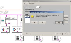
NetPro has displayed a popup before when I've tried to put an HMI address next to the PLC address. It said there should be an open address between. Other than that I've never been required to spread them out.
 
DesertDog said:
NetPro has displayed a popup before when I've tried to put an HMI address next to the PLC address. It said there should be an open address between. Other than that I've never been required to spread them out.

I have never come across that before..

I regularly use adjacent addressing, that's not to say I'm right and you're wrong though.

Paul

dpaddress.jpg
 
Address Error

If I move thre HMI (PC based) next to anything else I get a popup (See pic.). Help brings up this:

Help on Message 2775:815
Description of Error:

Your selected address may cause problems for the following reason:

· Address “0” is generally used by the PG.
Especially if the station is to be accessed via S7 routing (Subnet gateway), you can not use PROFIBUS address "0" for this station.

· According to the EN 50170 standard, volume 2, PROFIBUS, address “126” is not permitted. It is also not supported by every DP master.

· The node addresses of certain active nodes on the PROFIBUS must have a gap of at least one address between each node. STEP 7 assigns addresses for these nodes automatically to observe this rule.
Example for address gaps: You configured two CPU 315-2 without DP slaves. These are assigned the PROFIBUS addresses 2 and 4 automatically by STEP 7. You can change these addresses, but you must then ensure that there is an address gap.
Note: If you do not ensure that there is an address gap between active nodes, on certain active stations this may lead to errors in the data frames or even the failure of DP slave stations (does not apply to PROFIBUS-CPs in SIMATIC PC stations as active nodes).

To Correct or Avoid Error:

· Check whether the address can be used. If necessary, modify the address so that it conforms to the above rules.

error.jpg
 

Similar Topics

I am very new to Modbus and the industry, so forgive me if I am missing something obvious. I have known Modbus register addresses coming from a...
Replies
7
Views
227
I have a system using Rx3I CRU320 redundant CPU with Proficy Machine Edition Software. In the hardware configuration of each CPU module, under...
Replies
14
Views
388
See the screenshot of EIP tag list. We are trying to read in a digital input that is hard-wired. It is shown here as I31.1. I believe we cannot...
Replies
7
Views
282
Hello all. I have a Simatic SM374 (374-sxh01-0aa0) sim module. I am using TIA portal v.18. I can't find this module in my list of hardware devices...
Replies
12
Views
754
Hello, I have a device with 68 words input. But one block on the Devicenet Scanner is only 61 words. I am trying to map this device to 2...
Replies
3
Views
531
Back
Top Bottom