You are using an out of date browser. It may not display this or other websites correctly.
You should upgrade or use an alternative browser.
You should upgrade or use an alternative browser.
AD help with incoders
- Thread starter Rich1955
- Start date
elevmike
Member
Rich,
neither the 1st line or the 2nd line have anything to do whith the encoder inputs on X0 (phase A), and X1(phase B). The "Z" flag is connected to a high speed input like X2 (if you need it). If you want to reset the encoder to zero you can either use the high speed input on the bottom rung. C1 is unnecessary on the top rung for reseting the encoder to zero.
If you want to force some other value other then zero into the counter accumulator then you must disable rung 1 and enable rung 2, and disable rung 3. Then load and out to CTA 174.
You need code to setup the HSC for the configuration of the inputs. Check out page 3-24 of the DL-06 manual. Read the entire section and use the sample code. It would be way more educational if you had the PLC and encoder so you can kinda watch it in operation.
elevmike
Member
Rich,
What's the application?
Also it's best to use a subroutine to initate the counter setup. The sub will be active on the 1st scan only. Place the sub with the counter setup after the end statemnt to save on scan time.
What's the application?
Also it's best to use a subroutine to initate the counter setup. The sub will be active on the 1st scan only. Place the sub with the counter setup after the end statemnt to save on scan time.
High Speed Food Packager
The application is a high speed food packager which I haven't done in 4 years (with new updates and 120 RPM). Time to remember the old tricks and add some. The additions require me to rethink the hole program. I got to addmit I'm a little rusty just trying to get back into it. Her is what I got so far for the base program and I'm not done.
What I'm trying to do is remember the possition on power up.
Last edited:
elevmike
Member
Rich,
I take it the encoder/counter is only for one direction?? Please explain the application/purpose of the encoder/counter.
I take it the encoder/counter is only for one direction?? Please explain the application/purpose of the encoder/counter.
One direction
The incoder is hooked to the AC main drive and a different possition of the drive other function have to happen like two other servo drives moving parts, vacuum comming on, telling product when to feed. The incoder tells everthing when to happen and for how long and are adjustable from the Touch screen, when you change speed you have to tweek the timing.
The incoder is hooked to the AC main drive and a different possition of the drive other function have to happen like two other servo drives moving parts, vacuum comming on, telling product when to feed. The incoder tells everthing when to happen and for how long and are adjustable from the Touch screen, when you change speed you have to tweek the timing.

elevmike
Member
Re: One direction
Huh??? Not trying to be funny, but is english your second language? Could you break that down for me a little more? Im not getting the picture..
thanks..
Rich1955 said:The incoder is hooked to the AC main drive and a different possition of the drive other function have to happen like two other servo drives moving parts, vacuum comming on, telling product when to feed. The incoder tells everthing when to happen and for how long and are adjustable from the Touch screen, when you change speed you have to tweek the timing.
Huh???
thanks..
Mike, I think he means the following:
Encoder is attached to the drive.
The machine starts, at position "zero" ...
If the position is between 10 and 50 -> open the vacuum for the gripper
If the position is between 100 and 150 -> close vacuum
If the position is between 200 and 250 -> apply glue
And so on...
Encoder is attached to the drive.
The machine starts, at position "zero" ...
If the position is between 10 and 50 -> open the vacuum for the gripper
If the position is between 100 and 150 -> close vacuum
If the position is between 200 and 250 -> apply glue
And so on...
Sister machine
The sister machine was sold as is with no program because the gentalman before me did not know the machine. I received a call to do the present machine to help the people out. I know the machines before they had the servo drives and other add features so I have to update my program to add these.
Now my first step is the incoder. I can't just power down the machine because I loose all position with the 260 CPU ( or can I)?
The older machines did not matter because everthing was cam driven.
I have two choises to handle this. The machine stops in the same place every time (set that to 0) or put the count back into the counter when powered up. There is a third chose but I don't know absolote incoders.
Any thoughts?
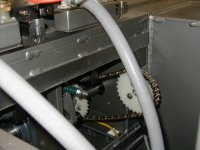
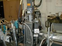
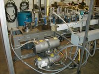
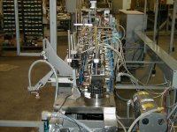
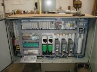
Look at this panel that never ran.

You can store the encoder-count in battery backed-up memory.
(be sure to install a battery or the back-up will only last for ?? days)
In DirectSOFT32 goto the menu PLC -> Setup -> Retentive Ranges to "activate" those ranges.
Or on inital startup you can go to a know position (the so called home-position) that can be detected by a proximity-switch and set your count to zero.
The use of an absolute encoder is only usefull if the machine does all the steps in one rotation. If it does, an absolute encoder is the way to go and really simple to use!
Best regards
I just looked at some code that uses an absolute encoder (from Kubler, it gives out a 10 bit binary code) and the only thing I had to do to get the position in BCD format was:
STR SP1
LDF X100 K10
BCD
OUT V520
So, at each scan from the program (STR SP1) I read the status of the 10 bits from the encoder (the wires from the encoder are connected to X100, X101, ... X109 so LDF X100 K10), converte those to BCD (BCD) and write that value into V520 (OUT V520)
Easy as can be!
STR SP1
LDF X100 K10
BCD
OUT V520
So, at each scan from the program (STR SP1) I read the status of the 10 bits from the encoder (the wires from the encoder are connected to X100, X101, ... X109 so LDF X100 K10), converte those to BCD (BCD) and write that value into V520 (OUT V520)
Easy as can be!
Similar Topics
please help me . I have to make this ladder diagram and I can’t figure it out :(
- Replies
- 12
- Views
- 182
Hi Everyone,
i was hoping for a little help with this module. i have data that needs to be read from a different plc through the Modbus plus...
- Replies
- 11
- Views
- 168
Hello,
I am trying to replicate a piece of logic on the PLC5 onto an SEL RTAC. I am using ladder on SEL and FBD. I am having issue on the ladder...
- Replies
- 11
- Views
- 158
HOW to communicate with OPTIX and Mitsubishi's Q Series PLC?? PLEASE HELP ME
- Replies
- 0
- Views
- 41
I'm fairly new to Rockwell software, I've had some basic training in the past but nothing too advanced. My company and I use Reliable products for...
- Replies
- 11
- Views
- 336


