Ote Otl

Martin T.

Member
Join Date
Aug 2002
Location
Northeastern Oklahoma
Posts
177
I think I'm losing my mind!
To make a long story short, guy has been working on a program for 22 months, half of it will only works in manual. So its given to me to debug and correct.
Everything starts out terrible, I've got 14 pages of notes on things I've corrected and have only got 5 out 12? rountines done. While I was testing the last routine I corrected I came across something that has thrown me for a loop. I'm using integer pointers to step through the routine.
At one point in the routine pressure between two cylinders needs to be equalized before the compressor is used(saves time) I'm using an OTE to energize a buffer bit for the valve. After the pressure is close to equal pointer goes to the next step, and the same buffer bit is latched to hold the valve open while the compressor is running. As soon as the pointer moves to the next step to stop the routine when the pressure set point is reached the latched bit unlatches itself.
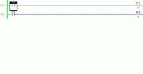
I can't post the full program for proprietary reasons. So I did a quick example of what I'm seeing.
My test setup:
SLC 5/03, 1747-L531E OS 302 Series C. Using RSLogix 500 ver, 6.20.

What have I forgotten? Or better yet can someone wake my brain up!!!!
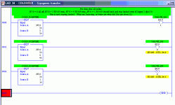
test_plcs.gif
 
Martin,
I'm not sure I understand the code you've shown... I'm not sure that b3:0/0 should be addressed in two different spots.... The ote could possibly? be occuring instead of the otl?
 
Last edited:
If N7:0 = 1 B3:0/0 should latch and stay latched if N7:0 = 3, right? B3:0/0 should be true and B3:0/1 should be true. The OTE for B3:0/0 should be seen because N7:0 doesn't = 4.
This is just what I came down to and it's just an example. For some reason the OTE should not affecti the OTL when the rung is not true.
this has had me scratching my head all day.
 
I tried this test code in a 5/04, and it appears that the ote is overriding the otl.... Whenever I toggle the test bit off and on, the b3:2/15 is following the test bit(b3:0/11)

testing2.gif
 
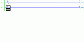
No, you're looking at it fine.... It just seems to something goofy in the AB instruction set... I tried this one in a 5/04, and when I toggle the test bit for the latch rung, b3:7/1 follows the test bit(b3:7/2) without even touching the rung with ote b3:7/1.... It seems that when you put the two rungs with the same address, the otl never takes precedence over the ote. I do know that in the help files for the ote instruction, it specifically says NOT to use the same address somewhere else......

testing3.gif
 
Martin T. said:
In my example if rung 1 is never true I don't see how it can affect it.

The fact that rung 2 is false is the very reason why it IS affected.

Think about how the scan operates. Let's say B3:0/0 got latched the previous scan.

When it reaches rung 2, if the rung is false, so B3:0/0 turns OFF.

If rung 3 is not true, then B3:0/0 will NOT be turned on again.

Another way to thing about it... OTL simply means "turn on this bit and leave it on unless it gets turned off elsewhere. Remember, OTU is NOT the only instruction that can turn it off. An OTE that is false says "turn this bit off". Many other instructions can affect the state of the bit as well... :nodi:

If I made no sense, someone else (I'm thinking Ron B...;)) might be able to explain it better.

beerchug

-Eric
 
I'm with eric on this one... Even if you latch the bit in for b3:7/1 and then toggle the test bit off, I can open up the data file for b3:7/1 and change the 1 to a zero......
 
I'm not entirely sure I understand the question but let me take a stab at this. Forgive me please if I am stating the obvious. It appears you are giving too much credit to the OTL instruction and not enough to the OTE.

  • N7:0 = 0
  • Then rung #1 is false and the OTE causes the output B3:0/0 to be reset
  • Then rung #2 is false and the OTL instruction does not execute
  • N7:0 = 1
  • Then rung #1 is false and the OTE causes the output B3:0/0 to be reset
  • Then rung #2 is true and the OTL instruction causes the output B3:0/0 to be set (last rung wins)
  • N7:0 = 2
  • Then rung #1 is false and the OTE causes the output B3:0/0 to be reset
  • Then rung #2 is false and the OTL instruction does not execute
  • N7:0 = 3
  • Then rung #1 is false and the OTE causes the output B3:0/0 to be reset
  • Then rung #2 is false and the OTL instruction does not execute
  • N7:0 = 4
  • Then rung #1 is true and the OTE causes the output B3:0/0 to be set
  • Then rung #2 is false and the OTL instruction does not execute

As I typed all this in, Eric beat me to the punch!! But since I entered all of this I figured what the heck.

OG
 
OK, maybe I'm thinking to much left to right. I know the OTE has been affecting it but I just haven't been able to explain it to myself why. Had it in my head that if the instruction before the OTE was false Nothing happens to OTE. It's the scan thing I'd better read up on again.
 
Martin T. said:
Had it in my head that if the instruction before the OTE was false Nothing happens to OTE.
This is where you're going wrong. If the rung with the OTE is false, then the bit addressed by the OTE is turned off. Your description fits the OTL - i.e. if its rung is false, the bit addressed by the OTL is not changed.
 
Tom, Eric, OG and Gerry thank you I appreciate the reply's, I'm awake now. Just looking at to much at once, I know how to make it work now. Been a long day, thanks alot guy's.


Yeah the OTE actually does something when it is false whereas the OTL does not
yep feeling pretty stupid now. šŸ™ƒ Time for some šŸŗ should have started this morning.
 

Similar Topics

I am a beginner at RSLogix 5000 and in ladder logic in general. I am tasked with making sense of an existing program and reprogramming it to make...
Replies
8
Views
6,047
Control logix CPU have a backup battery, this battery is not only backup user program, it also backup all data of All tags. now I have a...
Replies
2
Views
3,072
So I'm pretty new around here but I come looking for advice or suggestions to research. Im the plant electrician/SCADA guy for a warer department...
Replies
1
Views
25
See the screenshot of EIP tag list. We are trying to read in a digital input that is hard-wired. It is shown here as I31.1. I believe we cannot...
Replies
7
Views
281
Hello Dear users, I am writing about a problem that has been bothering me for a few days, i.e. I am trying to establish remote access to the Allen...
Replies
0
Views
87
Back
Top Bottom