Please elaborate

Chuck Krages

Member
Join Date
Dec 2002
Location
Ky
Posts
12
These questions concern diagrams found at http://www.plcs.net/dcforum/DCForumID1/2645.html
fig-1 thru 15 by Terry Woods March 2002

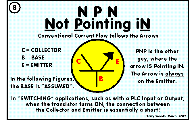
Question # 1. In fig-8, please explain this statement in more detail , especially about the short between the collector and the Emmitter if possible.

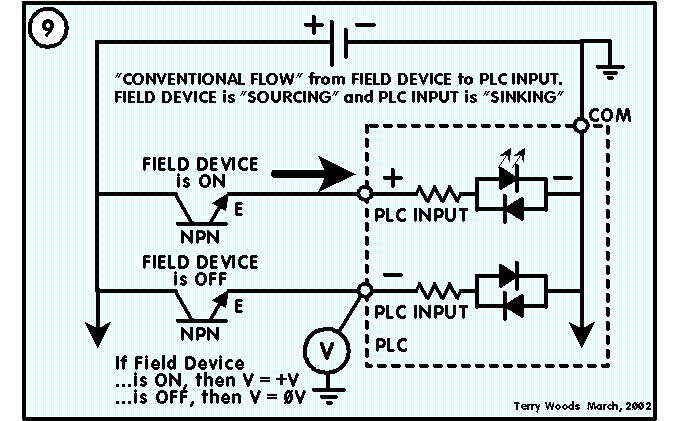
Question # 2. In fig-9, please explain "If field device is on
v = +v and so forth...

I understand the direction of flow , but I dont understand the purpose of the statement or should I say the relevance.
I'm missing something?
 
Last edited:
Question # 1. In fig-8, please explain this statement in more detail , especially about the short between the collector and the Emmitter if possible.


3ca3d8e811417795.gif


As it states in the figure, in SWITCHING applications the connection between the Collector and Emitter is essentially a SHORT.

In switching applications, such as in PLC's and ON/OFF Sensors, the NORMAL Mode of operation for a transistor is FULL-ON or FULL-OFF.

The FULL-ON or FULL-OFF condition is determined by current flow through the BASE of the transistor.

In Switching applications, when the transistor is to be ON, the current through the BASE flows at some maximum value (limited by the Base Resistor). Since this current is flowing at the maximum value, the transistor is said to be Driven to SATURATION. Being in Saturation means that the transistor is as ON as it can be. The transistor will pass whatever current, between the Collector and Emitter, that the LOAD will allow... that is, until either the transistor or a fuse (if you have one) explodes.

The FULL-OFF condition is produced when the current in the Base goes to zero, or there-abouts.

PAY ATTENTION: FULL-OFF IS NOT REALLY FULL-OFF!

In the Full-Off condition the current level between the Collector and Emitter is (or, at least, should be) very, very low, NOT ZERO, but very, very low. This is simply a transistor characteristic. The current that still flows, even though the transistor is "Full-Off", is called LEAKAGE; ALL TRANSISTORS HAVE LEAKAGE. If the current is low enough, then the load thinks the signal is OFF.

NOTE: When you work with transistors, everything is Relative! As in, Low ENOUGH, High ENOUGH, MORE Positive, LESS Positive, MORE Negative and LESS Negative... relative, get it?

So, when the transistor is "ON", it is Driven to Saturation and it will pass as much current as the load will allow. In that sense, the conection between the Collector and Emitter is essentially a SHORT.


Question # 2. In fig-9, please explain "If field device is on
v = +v and so forth...


3ca3d9191198c4a9.gif


As described in the previous answer, if the transistor is "ON", then it is essentially a SHORT. That being the case, then when the transistor in the field device is "ON", it is a SHORT and shows the FULL PLUS Voltage at the Emitter side of the transistor which is connected directly to the PLC Input terminal. The transistor will pass as much current as the "Load" will allow. In this case, the "Load" is the PLC Input.

The current through the transistor is limited by the LED (which doesn't provide much resistance at all) and the resistor. The resistor is the primary current limiter. The current should be limited to a value that won't destroy the LED.

As far as "Relevance", this information can come in pretty handy when you are trying to troubleshoot. If you know what should be going on then you can find your problem sooner.
 
Last edited:
Maybe the word SHORT is confusing? Here's a definition of short (as in "short circuit")...

short-circuit

\Short"-cir`cuit\, v. t. [imp. & p. p. Short-circuited; p. pr. & vb. n. Short-circuiting.] (Elec.)
To join any two points of a circuit, by a conductor of low resistance.
beerchug

-Eric
 
PAY ATTENTION: FULL-OFF IS NOT REALLY FULL-OFF!

This being true in a NPN circuit, can I assume that the opposite is true as far as V = +V would be V = oV in a PNP circuit @ the same location in the circuit ?

And thank you very much for your answer, I do realize how trivial this can seem to someone with many years of experience, so please know my appreciation of your time spent.

And thank you Eric, as they say "you hit the nail on the head"

And thank GOD there's no such thing as a stupid question.

Chuck
 
When I say "NO" I mean "YES", Damn it!!

Figure-10 shows that for PNP type Field devices, if the Field sensor is ON, then the "Short" in the that transistor ties the PLC terminal to the Negative side of the Voltage source. The PLC Terminal is seen to be "0-Volts" when the Field Device is ON.

So, Yes!... I mean, No!... I mean, in this case, the PNP case, YESDEVICE means NOPLC INPUT, which of course means YESPLC LOGIC!

YESDEVICE = Device is ON

NOPLC INPUT = 0-Volt at PLC Input

YESPLC LOGIC = Maximum current flowing through the Input LED in the PLC, therefore, PLC determines that the field device is ON.

In the NPN case, YESDEVICE means YESPLC INPUT, which of course means YESPLC LOGIC!

YESDEVICE = Device is ON

YESPLC INPUT = Full-Volt at PLC Input

YESPLC LOGIC = Maximum current flowing through the Input LED in the PLC, therefore, PLC determines that the field device is ON.

Clear as Mud??? If so, Now you are getting it!


3ca3d95911e65b92.gif
 
If Yes is No, and No is Yes, what's Maybe

Terry, I think you've done a fine job of confusing him.

When you say NOPLC Input, what you really mean is that the voltage at the PLC input point is Zero.

But, as you said above, When you work with transistors, everything is Relative! . The same it true of voltage. The PLC input voltage is Zero RELATIVE TO THE COM PLC point. The PLC detects that there is a voltage difference betwenn COM and the Inpt point, and sets the corresponding input register bit.

It doesn't matter what the absolute voltage is at the PLC input point. What matters is whether or not there's a differnce between COM and the point.

When a NPN device is On, there's V volts at the PLC input, and 0 volts at COM, i.e, a difference.
When a PNP device is On, there's 0 volts at the PLC input, and V volts at CON, i.e, a difference.

When a NPN device is Off, there's 0 volts at the PLC input, and 0 volts at COM, i.e, the same.
When a PNP device is Off, there's V volts at the PLC input, and V volts at CON, i.e, the same.


I'm just afraid that someone is going to read YESPLC Logic{/sub] and think in terms of -|/|- vs. -| |-, which is NOT what you meant.
 
Ok ! I think I'm getting it.

Would it be correct to say, ( if NPN & PNP are determined )

That P in N P N = positive or more correct +V at the input terminal,
when field device is ON ?

And :

That N in P N P = negative or more correct oV at the input terminal,
when field device is on ?

This is true only if we are talking about conventional flow,
and field device is sourcing in our NPN example
and PLC output is sourcing in our PNP example

AM I EVEN CLOSE ????????????

THANKS
CHUCK
 
ALLEN,

I do understand and APPRECIATE you saving me from my own ignorance.

And hopefully I can remember that the important point in this issue ,or lesson, is that the PLC determines it's results from
your statement about the difference in voltage from common to point of input terminal.

And to practice without looking:

with a NPN the PLC will read a difference between common(-) and input terminal reading (+) which tells the PLC that the field device is on.

with a PNP the PLC will read (+) on the common side and (-) on the input terminal side which tells the PLC that the field device is on.

Now I must assume that the PLC already knows if it is reading
a NPN OR a PNP. Don't laugh I'm just getting this.

Thanks Gentleman
Chuck
 
The plc doesnt care if its NPN, PNP, 120volt, 240volt, ac, dc etc etc. The inputs are designed to work with a specific voltage (type) range, in the case of NPN/PNP the norm is 24vdc. All the plc knows is there is a difference of POTENTIAL betweeen the actual input and the COMMON point for the Input, which in turn is recorded in software registers. Inputs are sometimes made to use Positive or Negative Logic BUT some can use either.

A sinking digital I/O provides a ground. A sourcing digital I/O provides a voltage source.

The main issue in the case of a plc that uses sinking or sourcing is not what happens but how its wired . An NPN OR PNP device is nothing more than a switch, it turns ON or OFF, with one it switches ON to allow a path for + positive current and the other switches ON to allow a connection to COMMON or GROUND (which are usually connected together). The real issue is understanding how to WIRE the device(s) to the plc properly but it helps more if you understand all the details associated with it.

Just to make it a littl simpler replace the NPN/PNP device with the symbol for a Pushbutton and think about it.
 
Last edited:
WHY???

Why is sinking called positive logic and sourcing neg.? If sourcing travels to sinking and conventional flow is + to - ?
If it's just because someone said so, OK.
But if there is a reason that will help me to understand it, please explain.

I don't want to overlook the reality of physical troubleshooting.
I want to drive the car , not just explain how it's done, so I appreciate your input very much RSDORAN.

And what are some examples of different wiring diagrams for NPN and PNP type switches. Such as a three wire prox. switch NPN verses
a PNP.
Realtime like a prox that spots a target and transmits signal to PLC,
or something like that. Whew, sorry if I'm slow.

Chuck
 
I will try again to explain, I am not as elaborate or eloquent as Terry and others but hopefully you will understand.

Sourcing input implies that the plc input "load" HAS A SUPPLY source voltage.

Sinking implies that the plc input "load" has a connection common to supply voltage.

Consider a simple circuit that consists of one digital input connected to a digital output. The circuit needs a voltage source, a ground, and a load. A sourcing digital I/O provides the voltage needed for the circuit. A sinking digital I/O provides the ground needed in the circuit. The digital input provides the load required for the circuit to work.

Figure 1 shows a sinking digital output that is connected to a sourcing digital input. In this circuit, the sourcing digital input provides the voltage and the load. The sinking digital output controls the line by using a transistor to leave the line high (at +V) or to ground the line to 0 V.

Figure 2 shows a sourcing digital output that is connected to a sinking digital input. In this circuit, the sourcing digital output provides the voltage and the sinking digital input provides the load and the ground. The digital output controls the line by using a transistor to leave the line at 0 V or to raise the line to +V.
sourcingdigital.bmp


Because you need both a voltage source and a ground in order to create a complete circuit, you need to have a sourcing input or output connected to a sinking output or input. If you wish to connect a sourcing input to a sourcing output or a sinking input to a sinking output, you will need to add an additional resistor. Lets work on that after you get this.

You did ask WHY and I almost didnt respond to that, I stated in a sense what I thought was more important...ie wiring the device according to manufacturer specifications so take a look at this:

http://www.cascadecontrols.com/Support/Sink_Source.html

As I stated before whether its NPN or PNP its a transistor device being used a switch. I deal with photeyes, proximity sensors, switches etc daily and the most important thing is that the device turns on/off and provides a connection.
 
Last edited:
rsdoran said:
...Just to make it a littl simpler replace the NPN/PNP device with the symbol for a Pushbutton and think about it...

Good example Ron! It might be helpful to expand on that example...

Chuck, imagine the N.O. pushbutton contacts are connected to the emitter and collector, and the operator as the base. Or, as Terry would say "YOU ARE THE BASE" or "BE THE BASE"... :p

beerchug

-Eric
 
So the transistor is the switching device as in NPN and PNP type?

In other words when input is sourcing, it provides the voltage and the load to the sinking output, and the sinking output controls the line using a transistor or switching device that could be either
a NPN or PNP depending where the line is left at,(+ or -) when switch is on or off

When output is sourcing, the output provides the voltage only and the sinking digital input provides the load and the ground. And the line is controlled by the outputs transistor to leave it at + or -.

And how the line was left (+ or -) would determine the type of transistor to be NPN or PNP.

Either way the output uses a transistor to control the line
or can I say? (A switch to turn it on and off)

sourcing I/O provides the voltage needed in a circuit
the sinking I/O provides the ground needed in a circuit
The digital input provides the load for both. (just repeating)
 
Are you telling me that as I push a N.O. push button it would be the difference of the two contacts being fed in
one diagram + on left and common on the right
another diagram common on the right and + on the left ????

That is of course: contacts that close the circuit between the COLLECTOR and the EMMITER.
because I am the BASE
 

Similar Topics

Hi , Where i can find Mitsubishi PLC Card end of line & replacement model details. i am looking for Q02CPU replacement model. Please advice. thanks
Replies
2
Views
126
Hello, I am trying to get a Yokogawa Hart pressure Transmitter and a Rosemount Temp Transmitter to read on a 1769-IF4 module on an L33ERM...
Replies
10
Views
375
Please help me, I have solve many week but still not solve it. I found trouble of factory talk studio when I set tag by browse address of OPC...
Replies
0
Views
117
Hello Everyone, i Have im my Industry a Endress & Hauser Promag400 this has a screen that constantly have that error, it says to wait, somebody...
Replies
2
Views
475
Back
Top Bottom