Shunt

PERSPOLIS

Member
Join Date
Jun 2002
Location
ontario
Posts
295
HI EXPERTS

I have a panel meter which indicates DC current from 0 to 150 amperes.
The meter has resistance of 20 ohms and requires 0 to 50 mili volt . I need to calculate the value of shunt resistor .
My DC source voltage which is connected to meter is 10 v at max
Thanks experts
 
The calculation is simple Ohm's law: V = I x R. However, if I am envisioning your proposed solution you are going to have trouble finding a 1.5 kW resistor.

You should consider using a signal conditioner or amp transmitter. Advanced Aerospace Components and N-K industries are two possible sources.
 
deja vu

We've been through this before.
http://www.plctalk.net/qanda/showthread.php?s=&threadid=1891
Questions for Perspolis:

If your meter gives full-scale deflection for 50 millivolts, what do you think will happen when you apply 10 volts?

Are you familiar with Ohm's law?

If you apply 50 mv to a load of 20 ohms, how much current flows? What if you apply 10 volts? Can the load dissipate the heat?

If you want a current of 150 amps to give a voltage drop of 50 mv across the load, what resistance should the load be?
 
Last edited:
PERSPOLIS

I am having trouble identifying what you are trying to do. Are you wanting a voltage divider circ or what? Are you trying to operate a 50mv meter on 10v?
Why not drop a 50mv shunt into your dc circuit and connect your meter directly to the shunt?

Roger :confused:
 
If 50 mV provides full scale deflection and the source is 0-10 volts, doesn't he need a 3980 ohm series resistor instead of a shunt resistor? 50 mV across 20 ohms gives 0.0025 amps through the resistor. Putting a 3980 ohm resistor in series with the 20 ohms gives 4000 ohms. Putting 10 volts across the 4000 combined ohms gives 0.0025 amps through the 20 ohm resistor as before. The series resistor can be small wattage but hard to find that value. Anybody agree?
 
Godfrey

I think you will find that you are incorrect.

Perpolis has an ammeter that is scaled 0 - 150A. Full scale deflection of this meter is 50mV. The ammeter is required to measure the volt drop across this shunt, which is in parallel to the meter, so that the majority of the current flows through the shunt, probably up to 150A with very little current flowing through the meter itself. the shunt having a lower resitance than the meter.

Perpolis, as Roger stated, do you want to turn this 'ammeter' into a volt meter capable of reading 0 - 10V?

If this is the case, then my appoligies to Godfrey as he would then be correct, you do need a series resistor.

Paul.
 
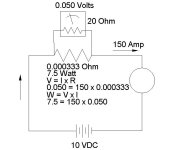
I guess we aren't so expert after all - this arrangement is feasible if he can get a 7.5 Watt or greater shunt resistor. I still think a transmitter is a more elegant solution, though.

scratch.jpg
 
Tom,
Just a few questions.
Why did you figure your resisters "shunts" wattage in your diagram using .050V instead of 10V?

Would you say that this is a parallel circuit? I can see that the shunt and the meter resister are parallel, so wouldn't they both have the same voltage drop?
Sorry for the stupid questions its just been a while since the electronics classes.

Thanks in advance.
Tim
 
I think I agree with the signal conditioner thing but it seems to me the math is wrong. I stayed out of this because I didnt feel I could contribute anything but....

We have a 50mv meter with a 20 ohm resistance, 50mv/20=.0025apps or 2.5ma
That means the shunt would have a current of [email protected], this would be a 0.066ohm resistor

Ok lets see if we cant make all of this more realistic. They make shunts designed for applications like this:
http://www.flex-core.com/page167.htm

http://www.deltecco.com/MKA-DC.html

http://www.hobut.co.uk/shunts.htm

The manufacturer of the panel meter probably offers a shunt to work in conjunction with the meter at the amp rating you need.

BTW Tim dont forget the load resistance, source is 10v and the parallel ckt is in series with it. The voltage and current seen at load must remain 10v@150amps therefore you create a parallel ckt in series to the load.
 
Last edited:
Ahh, Thank You RS
I figured the same as you RS. I looked at how musch current was needed to give a full scale reading of 150 amps using 50mv with resistance of 20ohms. .050/20=2.5ma I subtracted this from 150 amps which gave me 149.9975amps. I then took the 149.9975 and used R=V/I which is 10V/149.9975amps=.0666 or 66ohms.

Great refresher course.
Thanks Tim
 
Actually I think it came out to 0.066334.... which is 0.066ohms not 66ohms, close enough to government work though. They make shunts in the .03ohm range so this isnt an unusual situation.
 
Did you guys notice that round thing on the right hand side of Tom Jenkins' drawing? That represents the motor armature and that's where the 9.95 volts is dropped. At 150 amps that's very close to 1.5 kw.

However, if you relate this to the previous thread (see my previous post), I think you'll find that there probably is a signal conditioner supplying an analogue of the armature current to a SLC which has an analogue output (0-10 VDC) to the panel meter. According to P's posts, there is a 20K resistor in parallel with the meter.
What are the odds that something's been toasted?
 
Did you guys notice that round thing on the right hand side of Tom Jenkins' drawing? That represents the motor armature and that's where the 9.95 volts is dropped. At 150 amps that's very close to 1.5 kw.

you are correct

According to P's posts, there is a 20K resistor in parallel with the meter.

you are incorrect as is stated by this thread:
The meter has resistance of 20 ohms and requires 0 to 50 mili volt

I stand by my statements that shunts are created for this purpose and are easily obtained.

What are the odds that something's been toasted?
If this person connected it I agree that is a good probability.

Nothing personal but the poster doesn't have a tendency to be very accurate when stating things, this leads to assumptions and we all know what that does.
 
Last edited:

Similar Topics

Good evening all! I hope you folks are doing alright today, as I've got a situation that I believe I've come up with a solution to but I wanted to...
Replies
1
Views
436
We are in the process of installing a new DC drive to replace a 1373 series Speedpak drive. There are 8 leads coming out of the motor -- Two for...
Replies
5
Views
845
Hello Folks, I hope you are keeping well. Im a mechatronics instructor at a community college and you lads have helped me bigtime in the past. I'm...
Replies
13
Views
4,578
Hello guys, I will try to summarize my problem as follows Problem: ---------- I want to monitor the status (& also remote control) of a UL489...
Replies
3
Views
3,293
Hi all Hoping somebody can help me here. I have a system equipped with 500A / 50mV shunts and need to measure system current in the realms of...
Replies
4
Views
1,638
Back
Top Bottom