Schematics technique

Join Date
Apr 2002
Location
Just a bit northeast of nowhere
Posts
1,117
For simplicity, let's keep this hypothetical :

You are diagramming the interconnections between two machines. Machine A sends three +24 VDC signals to Machine B, via interposing relays. Machine B returns the favor.

Where the relays are located physically is irrelevant to my question - I'm not trying to rehash the "wet-dry contact" issue :) What I want to know is, how do you like to see this sort of relationship drawn on a schematic?

For instance, would you work it into the regular IO circiut diagrams somehow, or dedicate a page specifically to this relationship? If the latter, what do you do with the IO on the normal page? Ignore it? Use a line jump to the page? (Hmm, may have just answered myself...)

I'm really curious to see your individual approaches.

Thanks!

TM
 
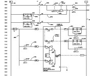
If the devices are all used in the same schematic (relay isolation between a plc and a drive in the same cabinet, for example) I usually show the relay coils on the sheet where they are driven and the contacts on the sheet where they are used. I then use cross-reference numbers between them. The upside is it shows the information where it is actually relevant and doesn't split a single device across multiple pages (except for the relay, of course).
The downside is that someone looking at the drawing can't get the big picture on a single page. Also, drawing modifications may change the cross-reference locations so you have to babysit them too.

With machine-to-machine interface where I don't have control of either the use or source of the signal I do something similar except without the cross-reference. With signals from somewhere else I show the contact in the normal logic with a note that it says 'from customer' or something like that. For signals from me I show the coil where it would normally be driven. I then cross-reference to a separate page that shows the interface signals as contact closures with functional descriptions and the general note 'To Customer'. If I get the signal and source information after install I will update the drawing with the additional information.

Hope that's what you were asking about. It will be interesting to see other people's methods since I'm not sure I'm 100% happy with what I just described.

Keith
 
Yep, that's the stuff!

That's exactly the sort of information I'm looking for, even better since it wasn't either of the ideas I tossed out as examples.

Thanks for the answer, and I too am anxious to see what sort of responses we get.

TM
 
most guys do it the way you do. I prefer to show the outputs as if they were contacts, and the inputs as if they were pilot lights. That lets me se at a glance the ineterlocking with other equipment or external circuits. I cross referenece the I/O to my point list.

bfv.jpg
 
Tim I will see if I can copy some drawings as examples tomorrow. I have some European machines, German and Italian, the older machine schematics seem to have a method that took a learning curve to follow. The newer German and Italian machines follow the same method (maybe its an IEC guideline, I havent determined this as fact yet).

Either will use block reference with the contact device from the other machine OR a termination point and wire number with reference to machine/wire number/schemtic page. I will see if I cant scan some to show this in better detail. Since these machines have multiple page schematics the page/machine/wire number reference makes it a little easier to track down problems.
 
Ian,

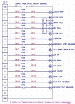
This is the other sort of example I was describing. You refer the reader to a separate drawing, with all of the wiring connections for the device shown on that page.

Ron,

So the euro's use both? Now I wonder what criteria makes them decide on one or the other! Ahh, shoot, now I have stress... :p But I'm looking forward to the examples.

Lastly, what brought all of this on is, I'm re-writing a few schematics, and I'm not satisfied with the quality and with the time it takes to generate them.

I'm trying to identify: 1) What is the best approach to show relationships between controllers and peripheral equipment (as opposed to a simple solenoid or lamp? 2) What is the best approach for documenting interposing relays, specifically, same page or separate page? 3) What in a schematic can be omitted for clarity's sake without sacrificing tracability?

Probably should have said that in the first place, huh?

TM
 
Last edited:

Similar Topics

How much detail do you go into in your schematics? I've seen schematics where every termination is labelled, every cable line is explicitly...
Replies
8
Views
5,382
Just a quickie, opinion poll When I draw an output circuit with an interposing relay, I draw it as follows O +24 COM I I...
Replies
0
Views
3,380
hello i have LOGO! 12/24RCE and i am looking for a schematics of electronic board. Or if someone know what is the burned component on the photo.
Replies
4
Views
1,393
Hi, new member looking for help trying to understand why it is I have no problems going through hard wired electrical schematics, but struggle...
Replies
8
Views
1,911
I'm starting a large project using a Beckhoff controller and I/O. Their modules are what I'd call the "slice" style, similar to Wago and others...
Replies
2
Views
1,797
Back
Top Bottom