Analog output - on board S7 CPU 313C

PLCKeef

Member
Join Date
Nov 2005
Location
Australia
Posts
68
Hi all
I am having some trouble working out the address of the analog output for my 313C S7 CPU.
The analog input seem to be correct at PIW 752, and I have scled the raw data etc and ot works fine.
Scanning the manuals it seems that the analog out put is PQW752 as well ?
I have tried it and I'm getting nothing.
Anyone had any experience with the onboard analog outputs ?

Any idea on what slot address it might be for the on board analog inputs and outputs , I know on S5 plc the on board analog is slot 8.

Upgrading to S7 slowly.....
 
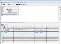
These addresses are default for CPU-313C, but they may be changed in HW Config. First check hardware configuration in you project.
 
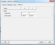
Like the Analog inputs, you must set the parameters (current or voltage)for the outputs as well.
You have scaled (probaly with FC105) the data from the analogue input, before you send data to the analog output, use FC106 to unscale it. I have worked several times with analogue I/O on the 313C and 314C and it works fine.
 
Ok thanks
Any tips on using FC105 etc
I am using S7 lite and FC105 etc seem to want a slot address , I'm at home today so can't check it out , any idea on what slot the onbaord analog inputs and outputs are.
An example would be most helpful.
I have done the analog input myself without any functions , it was a steep learnign curve but I got there , converting to 32 bit real number etc etc , I hope FC105 makes it easy ?
 
PLCKeef,

Are you using the "FC105 SCALE CONVERT" block, located in "Libraries - Standard Library - TI-S7 Converting Blocks?
That block does not need a slot address. in STL it looks as follows:

Call "Scale"
IN:= This is the analog input e.g. PIW 752
HI LIM:= High limit of the scaling e.g. 100
LO LIM:= High limit of the scaling e.g. 0
BIPOLAR:= if the input (here PIW752) goes negative (e.g. -10V), BIPOLAR =true. if not BIPOLAR = FALSE
Ret Val:= status feedback from the function (see help for values) "0" = all is well
Out:= your analog input scaled and ready to use!
 
Thanks

It worked :)

Next is the PID block , has anyone used the PID block ?
I will have a look into and probably have some questions next :)
 
If you use a PIB block, be sure to call it in OB35 = time interrupt (or similar). Doing that, you will have a fixed time interval that is needed for the I and D part of the PID regulator.
 
Plc s7-300, cpu313c

There are four temperatures i.e. liquid temperature, room temperature, warm temperature and cold temperature which you feed to input of PLC. Okay now, you need to get the PWM signal and peltier temperatures ranging from 10 degree celcius to 68 celcius. Keep in mind that you have also connected two relays i.e Solid state relay and mechanical relay to PLC and PE respectively.
Dear friends, Let´s develop the program. If you are successful, you are highly appreciated.
 
PLC S7-300, CPU313C

There are four analog and other four digital inputs to PLC. Analog inputs are various temperatures. Now, we need to get the signals for output temperatures and PWM. Current ranges from 4mA to 20 mA. As you know all the parameters of PLC S7-300 CPU313C , now let us start doing the program considering the above conditions.
 
S7 300 313C communication issue

Hi Experts,

I am also doing a similar project like this. The project details are as follows.
1) CPU: S7-300 / 313C
2) Analog input: 3, 4-20mA directly from the Level transmitter
3) Digital output: 4 , which turn the solenoid valve ON/ OFF

After reading this thread, got confused, if i connect the three inputs directly to the Analog channel, whether it will work without any problem?

They big issue is, i dont have internet connection at site to check or find answers for my doubts. Tomorrow is the first day i am going to start the project.

Please advise, how to connect the analog input to the cpu and i am using FC105 from T1-s7 converting blocks. But it is displaying as "Read Analog Value 464-2".

Please tell what HW config i had to check. IT is a 4-20mA signal. for that what setting i have to check.

I will update the status by tomorrow evening. if i come across any problems.
Regards
Mukesh
 
S7-300-313C PLC Analog output not working

Hi guys,
I have CPU S7-300-313C ( Cat No - 6ES7-313-5BE00-0AB0) DI24/DO16 and AI5/AO2.
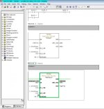
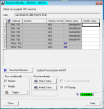
when I am trying to configure and use the AO channel PQW752 and 754 connected with a valve positioner, facing problem, it is not changing the output 4-20mA as per FC106 IN value.
I am using FC106 (Unscale) Block. (out Adress - PQW752)

kindly suggest which FC block I should use.

I have also doubt about analog output loop wiring, I need to know how many wires I need to connect for a 4-20mA current output. I guess only 2 would be enough. Are there anything i should care about?

I have searched the support site but unable to find relevant data (might be because of my pathetic search skills. )
so kindly provide any reference wiring diagram for AO chanel of CPU S7-300-313C

Refer Attached snapshot
you may send reference wiring detail on [email protected]

PIC1.jpg PIC2.PNG PIC4.PNG PIC5.jpg PIC6.jpg
 

Similar Topics

Hello! Hope you are great. I need to make a change in a PLC with ladder logic. I will mount a analog valve and I need to control it in ramp up...
Replies
7
Views
318
I have a 170AAO92100 card that I am interested in using as a 10 volt output. Is there setup that I have to do in order to change output or simply...
Replies
0
Views
86
Hi We're having issues with an FX1N-1DA-BD Analog output module. We're using an metallic contamination sensor MCS 1000 to detect particles. This...
Replies
1
Views
107
I am having trouble with getting no control of my analog output signal. I am using the SCL function block to control my analog output. The logic...
Replies
11
Views
243
I have a program that I am gradually piecing together (my first program). There are 4 cascading timers that turn Y001 and Y001 + Y002 on and off...
Replies
8
Views
542
Back
Top Bottom