S7-226 hooked with absolute encoder

suganya

Member
Join Date
Apr 2007
Location
coimbatore
Posts
10
hi all,Pls help..Our application requires an absolute encoder to be interfaced with an S7-200 plc to calculate the distance traversed by an object. As a beginner i want to know if the programming is similar to pulse calculation from an incremental encoder or does this require gray code conversions.we hav planned for an omron-E6C2-AG5C encoder.
 
you need to calculate the count the encoder inself gives the conted values in BCD form as shown in fig

manual is attached

count1.JPG
 
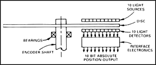
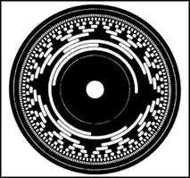
The absolute encoder is designed to correct this problem. It is designed in such a way that the machine will always know its location. Figure 10-112 shows an example of an absolute encoder. From this figure you can see that this type of encoder has alternating opaque and transparent segments like the incremental encoder, but the absolute encoder uses multiple groups of segments that form concentric circles on the encoder wheel like a "bull's eye" on a target or dartboard. The concentric circles start in the middle of the encoder wheel and as the rings go out toward the outside of the ring they each have double the number of segments than the previous inner ring. The first ring, which is the innermost ring, has one transparent and one opaque segment. The second ring out from the middle has two transparent and two opaque segments, and the third ring has four of each segment. If the encoder has 10 rings, its outermost ring will have 512 segments, and if it has 16 rings it will have 32,767 segments.

Since each ring of the absolute encoder has double the number of segments of the prior ring, the values form numbers for a binary counting system. In this type of encoder there will be a light source and receiver for every ring on the encoder wheel. This means that the encoder with 10 rings has 10 sets of light sources and receivers, and the encoder with 16 rings has 16 light sources and receivers.

The advantage of the absolute encoder is that it can be geared down so that the encoder wheel makes one revolution during the full length of machine travel. If the length of machine travel is 10 inches and its encoder has 16-bit resolution, the resolution of the machine will be 10/65,536, which is 0.00015 inch. If the travel for the machine is longer, such as 6 feet, a coarse resolver can keep track of each foot of travel, and a second resolver called the fine resolver can keep track of the position within 1 foot. This means the coarse encoder can be geared so that it makes one revolution over the entire 6-foot distance, while the fine encoder is geared so that its entire resolution is spread across 1 foot (12 inches).


0c7b7a87676.gif

Absolute Optical Encoder Internal Construction


0c7b7a87677.gif

FIGURE 10-112 Example of an absolute encoder wheel that shows the pattern of concentric circles. This diagram also shows the location of 16 light sources and 16 light receivers that decode the pattern of light as it passes through the 16 concentric circle patterns. (Courtesy of Analog Devices.)

Since the absolute encoder produces only one distinct number or bit pattern for each position within its range, it knows where it is at every point between the two ends of its travel, and it does not need to be homed to the machine each time its power is turned off and on
 
thanks alot praveen..We are planning to use exactly the one in ur manual..i jus had a glance of it..let me go thru properly..now, as the outputs are in BCD that part is clear.. but regarding the programming!!for incremental types say to measure the position of a rod moving up and down we use the encoder output phases A and B..how can that be done here?
 
count1.JPG


each line in the fig is one output from the Encoder if the number of increases then the accurecy will increase each output will connected to your Input module(take care about sink & source from encoder to the PLC input card)
i am not familier with siemens
 
ya tat i understand praveen..but my doubt is how the code is to be written for increment and decrement functions ie) up and down transitions..
 
If you can configure the abs. encoder that way --> it increments when it is rotating one way and decrements when it´s rotates otherway...
Then it is really easy to write your code, just couple of compare functions and it´s done...
 
no need for any calculation I hope abs. encoder hold incremnts when one direction movement & decrements when it is in other direction only you have to read the data
 
Hello guys;

Just a few points:
The S7-200 is designed for incremental encoders use (it has HSC inputs) and there are Tips and Tricks that cover this on the siemens website. Are you absolutely stuck on an absolute encoder?
If you have no choice, check this:
This is an absolute encoder signal, so it will be brought on parallel wires, not on a serial link. You don't count pulses, you read the status of each input (8, in the case of the Omron model that you mention) and regroup them in a byte. So you will need to reserve 8 inputs for this. The input byte will give you a Gray Code value.
Since the s7-200 is not designed to connect to an absolute encoder or to handle gray code signals, you will have to convert Gray code to Binary, probably in a sub-routine as you want this calculation done at each scan.
Here is a link to a ladder-logic implementation of a Gray Code to Binary conversion:
http://www.plcdev.com/using_ladder_logic_for_gray_code_conversion
The binary value you will get from the conversion will correspond to the number of steps you have moved from the original position (depending on the resolution/number of steps per revolution of the encoder used).
Hope this helps,
Daniel Chartier
 
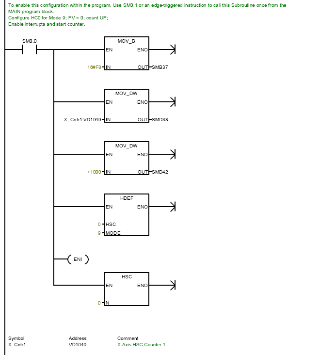
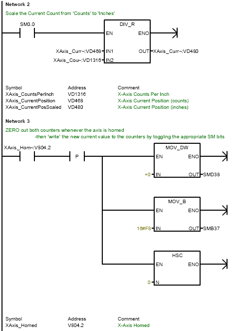
The S7-200 HSCs support A/B quadrature encoders too ('mode 9') - here's what works for me:

Initialize the HSC (use the wizard!):
S7-200HSCInit.png


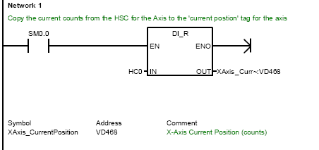
Copy HSC counts:
S7-200HSCCopyCounts.png


Scale counts to EU & Zero after Homing:
S7-200HSCScaleAndZero.png
 
Thanks to all for the response.. and special thanks to DANIEL for delivering exactly what i required.. and Praveen the o/p is ofcourse in gray and not in BCD.. so Daniel u mean to say that HSC holds good for incremental inputs alone and mere reading of the status alone is enough for absolute inputs.. rite? and gray to BCD conversions ofcourse after that..Hmm.. let me go on with the programming.. :) wil be back..
 
I would suggest setting up a High Speed timed interrupt and doing a Immediate read of the "bank" of inputs your interested in and doing the comparison there.


Nick
 

Similar Topics

Its a S7-200 part # 6ES7 216-2BD23-0XB0 A customer sent me one of these to extract the program out of. I have zero experience with Siemens S7...
Replies
5
Views
2,201
Hello everyone, I have inquiry for Siemens S7 200, CPU 226 CN. Its for Chinese market. Can anyone tell me how exact to take data from PLC? I've...
Replies
2
Views
2,643
Hi All, I am trying to set up the communication between a G304K200 and a Siemens S7-226 PLC via serial PPI but it is not working and I did a...
Replies
0
Views
1,417
Hi, Had anyone Have this problem, where the Siemen 226 CPU (s7 200CN) 6ES7 216 2BD23 0XB8 disconnect the Proface Model 3580207-02...
Replies
0
Views
1,194
hi all.. i have cpu226CN,,, i want to change my this china cpu with orignal CPU226.,, is this possible to do so?? Furthermore,, CPU226cn is...
Replies
2
Views
2,063
Back
Top Bottom