Relay bank wiring

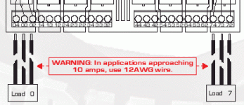
I'm guessing that the PDF diagram you're referring to is THIS ONE?

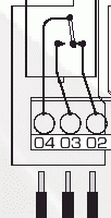
And is this the part that's confusing?
[attachment]
I see where you might get confused if you're not familiar with relays. You're probably saying "I only have 2 wires to connect, why does it shows 3 on the diagram!?!?". Basically, you'll connect your two wires to x4 and x3 if you want your external circuit to CLOSE when the output is ON. This is called Normally-Open (or N.O.). Most likely this is what you'd use, but if you want your external circuit to OPEN when the output turn ON, connect to x4 and x2. This is called Normally-Closed (or N.C.).

The "x" is replaced by whatever number output you're using. For example, if your using output #2, you'd connect your wires to 24 and 23 (N.O.) or 24 and 22 (N.C.)

Get it?

beerchug

-Eric

diagram.gif
 
This aux.-contact numbering is from EU n3-n4 where n is charge number of contact (or relay in this case) and 3-4 is no-contact and 1-2 is nc-contact (3-2 in this case, change-over contact where 3 is common).
Where n4 is common, that is not harmony with 'standard'.
 
Sorry seppoalanen, I accidentally chopped off the relay portion. Here's that part...
[attachment]
I agree that usually n1-n2 is N.C. and n3-n4 is N.O.

And yes, on SPDT (form C relays), n3 should be the common. If only everyone could agree to use ONE standard, our life would be much easier... :D

Although, the contact numbering used here is not all that uncommon. I've seen it a lot on stuff from Asia.

beerchug

-Eric

relay.gif
 
I gave up trying to figure out relay terminal numbering years ago - even models from the same manufacturere seem to vary widely.

javmen, I o find it helpful to skethc out the circuit for a single relay in very simple format, like the drawings in your circuits 101 class. That lets you make sure you have power in the circuit, and also lets you make sure your circuit is complete. The most common confusion seems to be how to hook up "+" to the commons on the PLC outputs, and how to tie "-" to the commons on the PLC inputs.

Code:
         C     X0
 ----------| |-----------(Coil)---
 |                               |
----                             |
 --                              |
----                             |
 --                              |
 |                               |
 --------------------------------
 

Similar Topics

Hi, I am using AB 5069-L306ERS2 CPU. My system should achieve SIL-2. I have safety door switches connected to AB 5069-IB8S module, and I want to...
Replies
1
Views
103
Hello, I need assistance in making a Relay operation that follows the given parameters: -if S1 is switched and S2 is at off, the Lamp 1 will be...
Replies
3
Views
106
Question to anyone with ideas about my thoughts on upgrading a very vintage timer, which is being used to switch between 2 5hp domestic water...
Replies
14
Views
430
I have an application where I want to use a safety relay in combination with a flame detector as the sensing element. The flame detector has relay...
Replies
23
Views
1,055
Back
Top Bottom