I'm finally trying to get my analog sensors to work on this plc (micrologix 1200) we have the analog module too. We are using a SCP command but we cannot get the input of this command to work. The error is either the word bit must be specified or something about configuration. Does anyone know what I'm doing wrong. Exactly how do you type in something for an analog input?
You are using an out of date browser. It may not display this or other websites correctly.
You should upgrade or use an alternative browser.
You should upgrade or use an alternative browser.
Help please!
- Thread starter PLCgirl
- Start date
Kim Gold
Member
Probably more specifics are needed in this questions
Allen Bradley Micrologix 1200 1762 something series C
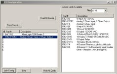
The expansion is 1762-IF20F2
The programming sofware RSlogix 500 version 6
My IR sensor is hardwired to input 0
Can anybody help me with these specifics?
Allen Bradley Micrologix 1200 1762 something series C
The expansion is 1762-IF20F2
The programming sofware RSlogix 500 version 6
My IR sensor is hardwired to input 0
Can anybody help me with these specifics?
Last edited:
Kim Gold
Member
Which slot is the card located?
What does you SCP instruction look like so far?
What does you SCP instruction look like so far?
Last edited:
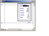
Unfortunatly I can't show you what it looks like but we finally got the input things to work so we think but we think our parameters might be wrong. What should the input min and max be (we are using voltage)? What is the scaled min and max? We were using some sample programming but we think that there min and maxes might be too much for us. Is there a way to figure out the min in max if they aren't constants?
Kim Gold
Member
Have you tried the AB.COM web site.
If you select OnLine Manual, then Control Processors, then MicroLogix 1200, then MicroLogix Analog Input/Output Module.
Allen Bradley Manuals OnLine
If you select OnLine Manual, then Control Processors, then MicroLogix 1200, then MicroLogix Analog Input/Output Module.
Allen Bradley Manuals OnLine
Kim Gold
Member
If the Input card is setup for 0-10 Volts:
0 volts should give 0 counts at card and
10 volts should give 32760
What are the specs of the IR sensor you are using?
If it goes from 0 to 10 volts the input min. will be 0 and the input max. will be 32760.
You can put a calibrator on the input card and see what it reads at 0 volts and see what it reads at 10 volts.
The scaled min. and max. will depend on what engineering units you are using.
If scaled min. = 0 and scaled max. = 100, the sensor will be scaled from 0 to 100 percent.
Kim you quickly becoming my best friend but I'm not quite there yet. On the IR sensors the max will not get any higher than about 2.65 volts the min is O. Is there a formula that I can plug the 2.65 in to get my max?
There is a 5 volts power supply to the sensors if this means anything
The error is an I/O configuration mismatch
I don't know how to show people exactly what we have but I can tell ya
Input I:1.0 (we are using input 0 of the expansion unit)
Input min is 0
Input max is 32760
scale min is 0
scale max is 100
I have also tried input min as -32767 to 32767 for a max
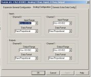
Our card is set for raw proportional data and is set for voltage reading 0 to 10 volts
Please please please please help me. Yes I'm a student but this isn't for a class. My prof and I are trying to learn analog I/O so it can be incorporated into the curriculum.
Last edited:
Kim Gold
Member
The min. and max. will still be the same.
When using voltage the card only has 1 setting, which is 0 to 10 volts. This means that at 0 volts you will see 0 counts. At 10 volts you will see 32760 counts.
So at 2.65 volts you will see something in between. You can see that this will effect you resolution.
Put a calibrator on input card:
0 volts = 0 counts.
10 volts = 32760 counts (check this)
2.65 volts = x counts.
Scaled min. = engineering units min.
Scaled max. = engineering units max. at 10 volts.
e.g. Try scaling to 0 to 1000
When input = 0 you should see 0 as output
When input = 10 volts you should see 1000 as output
When input = 2.65 volts you should see 265 as output.
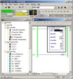

We keep faulting ... we go to error and it reads
"I/O configuration mismatch, check module 1. The expansion I/O configuration in the user program did not match the actual configuration, or specified a module that was not found, or the data size for the module was greater than what the module is capable of holding."
we have tried many things and your specific SCP program you showed us (thanks btw). We don't know how to check the card to see hows its reading right, except we have been using a fluke meter to check our voltages.
Kim Gold
Member
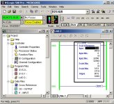
Here is an example using 2.65 volts scaled to 1000
You can see the scaled max. is set to 3775 counts.
2.65 volts = 8681.4 counts approx.
10 volts = 32760 counts
if you set the scaled min. = 0
and scaled max. = 3775,
you can see that when the Input shows 8681 the output shows 1000.
So 2.65 volts should show 1000 or 100% with a decimal point.
I am not sure about you configuration, I'm sure you have gone into I/O configuration and entered proper card in slot 1.
Also you need to go into advanced configuration and setup 0 to 10 volts.

Kim Gold
Member
Kim Gold
Member
For the analog configuration we have no control over it. It will not allow us to chooses anything. Our options are shaded/faded in the back. But they do say the same thing as you have.
We actually just figured this out. But everytime we fault we have to restart the software in order to be able to control this screen. We still don't understand why we are faulting?
We actually just figured this out. But everytime we fault we have to restart the software in order to be able to control this screen. We still don't understand why we are faulting?
Last edited:
Similar Topics
Hello,
I am trying to get a Yokogawa Hart pressure Transmitter and a Rosemount Temp Transmitter to read on a 1769-IF4 module on an L33ERM...
- Replies
- 10
- Views
- 364
Please help me, I have solve many week but still not solve it.
I found trouble of factory talk studio when I set tag by browse address of OPC...
- Replies
- 0
- Views
- 116
Hello Everyone, i Have im my Industry a Endress & Hauser Promag400
this has a screen that constantly have that error, it says to wait, somebody...
- Replies
- 2
- Views
- 466
After replacing the 70 with the 525, the PLC can read from the drive and recognizes it as online, but no commands are being listened to.
PLC is...
- Replies
- 1
- Views
- 543
To quickly test a plc output which is wired to a relay do I dob a cable between the output and 24vdc+ source I.e something with 24vdc+ live such...
- Replies
- 6
- Views
- 681


