Step 7 inter PLC comms

PLCdave

Member
Join Date
Apr 2003
Posts
15
Hi
I'm programming a Siemens S414 PLC in Step 7 and need to exchange data with a S414 and two S315 PLC's via Ethernet and several S315's via profibus.

I know I should RTM but if anyone can give me a quick example of how to read/write data from other PLC's over these type of networks I would be most grateful.

Also is it best to always read data or read and write data?

Is the transfer done by use of some message block function similar to RS Logix or is it possible to read or write to individual bits, bytes words etc.?

Thanks in advance

Dave
 
Profi comm

Hi:
You must use DBs to comunicate in Profi, the idea is like to mailboxes, you need configurate an in/out memory area with Step 7,
I never used Ethernet but I going to ask a workmate how to do it.

bye
 
PLCDave

To communicate via ethernet you can use the following blocks:

FC5 - AG_SEND
FC6 - AG_RECV

the above blocks can read/write up to 240 bytes of data

FC50 - AG_LSEND
FC60 - AG_LRECV

These two blocks can read/write up to 8k bytes of data.

There are a number of blocks that can be used for the profibus connections including FC1 - DP_SEND, FC2 - DP_RECV, if you use MPI for your connections (if you are not using a CP card) then you can use the following SFC blocks for your comms:-

SFC65 - X_SEND, SFC66 - X_RCV, SFC67 - X_GET, SFC68 - X_PUT.

There are some more blocks that can be used but that all depends on how your network is set up, whether your using configured/non configured connections or just glogal data communications.

I can't tell you if it is similar to RS Logix, but I would imagine that it would not be that much different.

Post back here if you need any more help / information

Paul
 
Paul
Thanks for the offer of help, it looks like the X_SEND and X_RCV will handle the profibus comms, however the help files aren't very informative, an example of how to transfer a block containing bits and words would help enormously.

Similarly with the ethernet I thought the AG_SEND and AG_RECV would be fine, however the help file says AG_LSEND and AG_LRECV must be used for 400 series CPU's. I am transferring data between a 414 and three 315's, do I need to use AG_LSEND & RECV for all comms? As above a specific example incorporating references to addresses and data blocks would be a big help.

Thanks in advance

Dave
 
PLCDave

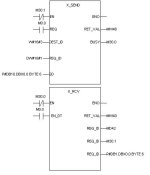
Hopefully the picture below will help you out.

As far as using AG_LSEND and AG_LRECV for use with a 400, I am not too sure on this, I would try and use AG_SEND and AG_RECV with the 400 and see what happens, I do believe that it works as I am sure that sometime in the past I have used these blocks for 400 - 300 comms. Remember that these blocks are for ethernet comms, not MPI or Profibus.

Paul

P.S sorry Dave I noticed my mistake on the picture, the bottom two right hand pins on the X_RCV block should read NDA and RD not REQ_ID

xsend.jpg
 
Last edited:
PLCDave,

I have just been reading my manual and in there it states that if you are using TCP for your ethernet protocol you must use AG_LSEND and AG_LRECV regardless of how much data you are sending.

That's something to watch out for. You can use AG_SEND and AG_RECV for ISO, ISO-on-TCP and UDP.

Paul
 
PLCdave said:
Also is it best to always read data or read and write data?
This is opinion only, but everybody writes own data when something have changed. Last data-element could be incremented byte, int or dint, so receive-plc can see when there are new-data present and it also can time-control it if needed.

Can you use MPI as well ?
 
Hello again
I've been away in bonny Scotland for a couple of weeks so haven't had chance to play until today. It seems that the FC50 AG_LSEND and FC60 AG_LRECV are the blocks to use, however I cannot find in the help files what the various connections are for and how to use them i.e:-
- for error at 0 or 1 what does the status represent?
- how do I specify what width of data and where it is (for send and receive)? What is the format of the pointer.
etc.
etc.

can anyone help please?

regards

PLCdave
 
Hello PLSDave;
First:
The help files in step 7 will give you all the info required for the parameters of the communication FCs. Open the catalog in the LAD/STL/FDB editor, choose the Simatic_Net_CP library, open the S&-400 section, choose FC50 (for example) and use the ? button of tyhe catalog to bring up the help file for FC5/FC50 (industrial Ethernet format). By using the >> button you will get to the «Formal Parameters» page of the help file; every parameter is described in full. For example, it explains that the ERROR bit must be exvaluated in conjunction with the DONE bit and the word value of STATUS;
Done=1
error=0
status=w#16#0000 means Job completed without error

Second:
the pointer format used in communication FCs is called an ANY pointer,; this type of pointer combines start point and length of memory data in one address. Look at the SD and RV parameters of the X-send X-rcv examples PLucas presented you earlier, these are ANY pointers;
«P#DB10.DBX0.0 BYTE 6 »
can be explained in this fashion:
P# indicates we are using a pointer format
DB10.DBX0.0 means we wish to point to the first bit of the first byte of DB10
BYTE 6 indicated the length in bytes that we will manipulate


so: if the data we wish to send is in DB22, and starts at byte 2, and we want to send 100 words of data, the pointer would be written

P#DB22.DBX2.0 byte 200.


Hope this helps,
Daniel Chartier
 
PLCDave

Hopefully the picture I have posted below will help you, the memory areas and bits ect, that I have put on the picture have just been plucked out of the air, you will need to change these to suit your program.

I have tried to help you out by giving a brief description of the pins for both blocks:-

AG_LSEND

ACT – if ACT = 1, the data is sent
ID – the connection number of the connection, this you will get during configuration of the card
LADDR – This is the module start address, again this will be got during configuration
SEND – What to send
LEN – how many bytes are being sent
DONE – This is whether the job was completed or not
ERROR – ‘0’ = no errors ‘1’ = error in sending data
STATUS – this will contain the error code is ERROR is ‘1’

AG_LRECV

ID – same as AG_LSEND
LADDR – Module start address, get during configuration
RECV – Where to put the received data
LEN – how many bytes have been received
NDR – this is ‘1’ when new data has been received
ERROR – as AG_LSEND
STATUS _ as AG_LRECV

Hopefully this will help you

lgsend.jpg
 
One final twist in the tail......

I want to transmit some booleans, some ints and some reals across these comms liks. I initially set up the send from a DB where I had declared INTs as in the PLucas example above (ie P#DB202.DBX10.0 BYTE 2), however this resulted in an error message saying illegal data type specified. To get around this I move the INT to MW 10 and send from Memory (ie P#M 10.0 BYTE 2). I have had to specify bytes in the receiving end DB too so perhaps I will now have to receive into Mem.

So it looks like I will have to put the sending end data into Mem locations and receive them into Mem locations then transfer them to DB locations accordingly to seperate out the bools, reals ints. Is this the correct thing to do or does someone know a more elegant method of communicating different data types ??? (the send and receive blocks will only accept Byte, Word or DWord)

Also does anyone have any neat error handling routines for the send and receive comms?

Thanks in advance

PLCdave
 
Hello PLCDave;
I would like to see how you built up your DB202. You should be able to fornmat the structure of the DB as you please, in BOOL, Byte, Int, Word, DInt and DWord types of data (not including all the Siemens complex types: TOD, S5Time, DaTime, Counter, arrays of data types, etc...). I have attached a typical DB I use for a client application.
The reason you can use M adresses is because the M-memory is not formated; Step 7 does not care whether you read/write to MW10 in bits (M10.0), bytes (MB10), integer (MW10) or word (MW10).
The structure of types in a database must be respected. If you transfer a Word value but try to write it over a BOOL address, you will get the error message you pointed out.
Make sure that Both the Send and the Recieve DBs are formatted in the same way, so that you data transfer is without problems.
Hope this helps,
Daniel Chartier
 

Similar Topics

Hi all, I'm looking for a steer using a pointer. The code is working in a fashion but i'm not setting the bit i require. The code looks at...
Replies
25
Views
5,038
Hello, Is it possible to perform operation like pointer on function. Regardless of value inside pointer or what ever variable I want to call...
Replies
2
Views
1,498
I would need advice in design which we are currently making in Step 5. Control system is based on Control modules which have defined structure...
Replies
6
Views
1,677
Hello Folks! I'm still trying to get the hang of using STL and Pointers in Step 7 (V5.5). For background, I'm writing a sample application...
Replies
7
Views
3,282
Hello everyone, I'm working on Step 7 Pro (TIA Portal), I would like to change the local time (GMT offset and Summer/Windter) of a S7-300 CPU...
Replies
3
Views
5,012
Back
Top Bottom