Pid Temperature Control

GOKALP

Member
Join Date
Apr 2003
Location
istanbul
Posts
8
hi everyone

I tried ziegler nichols method to find the ultimate gain and period while system is oscillating. but I was not able to have perfect oscillations. the 2nd oscillations max value was always lower than the 1st one. this was a simple heating machanism. I took the open loop response with the controller output %10 it took more than 6 minutes to reach the system to temperatue 160 C from 40. I calculated the time constant for the system it was about 5.5 minutes. For the dead time I am not that sure. I was not able to find the paramters using open loop response of zeiler nichols. but I think there was stg wrong with the calculation of dead time. do you know some other method to find the parameters using open loop response.

by intution I tried some PID parameters but by changing the setpoint sometimes system made large overshoots although I gave the setpoint with a ramp. ýthink because of the bias term.

instead of giving setpoint with ramp I am planning to use the Kp only and when the temperature is close the set point I will include TI term. Do you think it works?

when I was reading the Q&A's I remember someone was offering to use a table for bias term. I really wonder the details. If I use the bias from a table don't I need an integral term? how can I determine the bias. I believe open loop response of the system will give an idea.

regards
 
a picture is worth a thousand words -

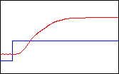
can you post a trend graph of your system's open-loop response? for example: something like this - but please make it as big as possible -
[attachment]

if you can do that - and if you can tell us
1. what the starting CV was (%)
2. what the ending CV was (%)
3. what the starting PV was (degrees)
4. what the ending PV was (degrees)
5. what the total x-axis represents - (time in minutes)
6. what the total y-axis represents - (temperature in degrees)

then we can probably help you work through the Ziegler-Nichols "reaction curve" method - or through any one of several other "open-loop" tuning methods -

zn open a.jpg
 
if you can do that - and if you can tell us
1. what the starting CV was (%)
starting CV was 0

2. what the ending CV was (%)

0.1 (%10)
3. what the starting PV was (degrees)
44 C
4. what the ending PV was (degrees)
160 C
5. what the total x-axis represents - (time in minutes)
minutes
6. what the total y-axis represents - (temperature in degrees)
in degrees

In fact I calculated the time constant as I find the the 0.63 PV max. At this value I looked at the time passed after the dead time. ( 3.5 minutes ) And by dividing 3.5 to 0.63 I found the time constant as 5.5 minutes. But to calculate Kp you also need a normalized CV and PV values. I remember with the output 0.05 starting temp was 44 C and end temperature 100 C. Dead time was 5 seconds. how do you calculate the parameters

Thanks
 
GOKALP,

If you want to set up a table for bias values, simply force the CV to a fixed value, say 25%. Wait for the system to stabilize and record the PV. This CV is what you'll use for the bias when your SP is the same as the PV. For example, if at a CV of 25% of maximum, your system settles at 250 degrees, when your desired temperature is actually 250 degrees, you'll use that 25% value as the bias.

Repeat for 50%, 75%, or for as many sample points as you feel necessary. Use linear interpolation for values between sample points. Continuing the example, say you settled at 400 degrees when the CV was 50%, and 500 degrees when the CV was 75%. Then for SPs between 250 degrees and 400 degrees, your bias would range linearly between 25% and 50%. For SPs between 400 and 500 degrees, your bias would range linearly between 50% and 75%.

With a method like this, you may find that you can control the system adequately without the need to use any integral at all. Essentially, what you're doing is making the best approximation of the control in open loop, and limiting the PID calculation to as small a percentage of the final CV value as possible.
 
Good so far...

Actually the time constant is 3.5 min. The time it takes the PV to change the 63% from the initial value.

GOKALP, are you an engineer? I can get more technical if you are.

Your openloop system response is

PV(t) = SP-(SP-PV(0))*exp(-t/3.5)) where t is in minutes.

The dead time may be the result of a second real pole. This happens when the temperature sensor takes time to change in response to the system heat changes. 5 seconds is pretty short and we can safely ignore it.

I will write more later when I am not at work.
 
gokalp,

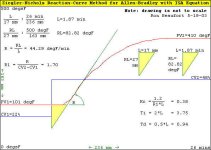
if you're serious about the ziegler-nichols method, here's an example that i put together in between customer calls - i can't guarantee that there are no typographical errors, etc. since i didn't have much time to proof read it - if you can post the trend and the information that i asked for earlier, then i'll try to run your system through the same type of exercise (assuming that i have some extra time tomorrow) -

[attachment]

anyway, you're in good hands with Peter and Steve - good luck

PS - for those that are interested, here is a handy link to the original Ziegler-Nichols publication (circa 1942) - now available on the web - courtesy of Mr. Walter Driedger and his excellent site -

classic PID loop tuning - from the days before PLC's

zn open b.jpg
 
Last edited:
Now for the SP.

It has been pointed out that step jumps in the PV causes the integrator to wind up and cause over shoot. The solutions are to not use the integrator or to avoid set jumps in the PV. The PV should be ramped from one set point to another. The question is how fast? The answer is simple, not any faster than the system can respond. In the GOKALP's system the response is:

PV(t) = SP-(SP-PV(0))*exp(-t/3.5)) where t is in minutes

Therefore the set point should be ramped as follow:

SP(t) = SP-(SP-SP(0))*exp(-t/3.5)) where t is in minutes

Where:

SP(t) is the current set point that should be used as the PID reference.

SP is the final desired set point.

SP(0) is the initial set point before the change.

One can see that there will be no error in the ideal system and the PID will contribute nothing to the control output. This is good because the integrator is not winding up. The bias ( see Steve's post above ) term will supply all the output until an error occurs.

There is no point in forcing the system faster than what it can naturally respond. Think of a swing.

Advanced Bias estimation. A simple look up table will do wonders but what if the open loop control output is a function of two functions? In motion control we use velocity and acceleration to compute the feed forward ( bias ). In the case of an oven, bias can be a function of desired temperature and also the rate at which material is moving into and out of the overn. This still requires a trial and record procedure much as Steve posted above, but one would also need data for different feed rates. From this data one can use the least squares algorithm to compute a open loop output function ( bias ) as a function of both desired temperature and feed rate.

It is possible to end up with a function that looks like this:

Bias = SP * 36 + FeedRate * 87


So how does one take the equation:

SP(t) = SP-(SP-SP(0))*exp(-t/3.5)) where t is in minutes

and convert it to an equation that looks like this?

SP(t) = K * SP + (1-K) * SP(t-1)

I have posted this info before, but no one seemed to care at the time.

More to come.
 
more information

Mostly what you people are talking about looses me.
And I have a whole lot of PID loop controllers in my plant that are my responsibilty.
This information has been explained to me more than a few time, but I really still just don't get it.
Is there a web site or some place that will break this down in a way that even this novice might be able to understand. small words might be best.
 
Source

mrdegold:

I'd recommend a book "PID Without the Math" by David St. Clair, which is available HERE.

Of course, where I think Peter is about to head is with Laplace Transforms, which requires a couple of years of calculus under your belt.
 
No Laplace.

However, GOKALP is the first on this forum to make an effort to find out what his system is like. With this information one can add another feature to the PID control which is ramping the set point at a rate the system follow. This avoids integrator windup.

Now we need an pracitical equation for ramping the SP derived from the time constant.
 
This is Interesting...

Peter,

It's been a while since I did any open/closed loop system analysis with transfer functions and LaPlace transforms, but where did you come up with the open loop transfer function of:


PV(t) = SP-(SP-PV(0))*exp(-t/3.5)) where t is in minutes.


Now a couple of questions..

1) Is the (SP-PV(0)) describing the lag time??
2) Is the exponentional function the characteristic of the heat transfer??

I should have a better idea of what you are saying, and was taught it in school, but never really got a good grasp of it. I'd love to learn more, as we have many processes where modeling, and I do believe modeling has tremendous potential.

Andrew
 
Re: This is Interesting...

Andrew Evenson said:
Peter,

It's been a while since I did any open/closed loop system analysis with transfer functions and LaPlace transforms, but where did you come up with the open loop transfer function of:


PV(t) = SP-(SP-PV(0))*exp(-t/3.5)) where t is in minutes.

It is a solution do a first order differential equation. I do these in my head from experience. I don't want to explain how as there is plenty of text on this.


Andrew Evenson said:

Now a couple of questions..

1) Is the (SP-PV(0)) describing the lag time??

No, it is there difference between where the PV at time 0 ( initial temperature ) and the SP ( Set Point ). As time goes to inifinity exp(-t/T) approaches 0.

Andrew Evenson said:

2) Is the exponentional function the characteristic of the heat transfer??

Yes, and many other functions. Heat transfer is like charging a capacitor through a resistor. At time 0 the charge on the capacitor is 0 so the current flow is I = (Vs-Vc)/R but as time increases the voltage on the capacitor rises so the current changes so the difference between Vs and Vc is less. This means the capacitor charges at a decreasing rate. Heat flow is also proportional to the differences between the hear source and what is heated. At what is being heated increases in temperature to that of the heat source then less heat will be transfered and therefore it will not heat up as fast. This also applies to bleed-and-feed operations where material is being mixed or diluted.

Andrew Evenson said:

I should have a better idea of what you are saying, and was taught it in school, but never really got a good grasp of it. I'd love to learn more, as we have many processes where modeling, and I do believe modeling has tremendous potential.

Andrew

Software models are great for testing. I don't need to worry about breaking anything and I can also exactly reproduce any mistakes. This allows me to learn at a far faster rate than the average person. It is a shame that most people do not have a system with which to experiment. I have posted some links to some spreadsheets in the past on this forum. They simulate second order motion systems. I have learned a lot just using excel spread sheets. I also have a package called MathCad and Matlab although I don't use the Matlab as much as I should.

I also use models to do a sanity check on my customer designs. This keeps them from designing a system that can't be controlled by even the best controllers. Can't violate the laws of physics you know.

There are heater/termperature control simulators on the web.

What does this have to do with PLCs? Many of the motion controllers actually fit in the PLC rack. The others communicate with PLCs using a field bus such as Profibus DP or Etherenet.
 
more PID

Peter

You mean using a ramp function as a delay of time constant 3.5 minutes. Isn't it a solution to use a proportional control until you reach some point near the set point and include integral term. So you do not have to deal with ramp function.

I just wonder why the system does not oscillate perfectly. The PV's max. point isn't the same but always lower than the previous. But note that I believe I calculated the dead time wrong. It should be stg around 0.5 minutes.

""""From Peter's message
So how does one take the equation:

SP(t) = SP-(SP-SP(0))*exp(-t/3.5)) where t is in minutes

and convert it to an equation that looks like this?

SP(t) = K * SP + (1-K) * SP(t-1)

I have posted this info before, but no one seemed to care at the time.
"""""

I did not understand why you convert the formula to

SP(t) = K * SP + (1-K) * SP(t-1) and what for to use it?

I also want to include a filter for the PV to be used with derivative term. I think I should also use a time delay of some time constant. Do you know what is behimd the derivative filter.

RON, Regarding zeigler nichols open loop response there seems some problem. If the max. temperature PV2 is not 500 but 1000 then the Kc term will be doubled. How do you determine the max. temperatue.I believe there must be some kind of normalization.
 

Similar Topics

I have S7 1512C controler for controlling 48 PID temperature loop, the output is PWM. Please I need the best, most efficient way to write the...
Replies
13
Views
603
I have PID temperature control which will connect to Beckhoff EL4004(0v-10v). How I can program it to let EL4004 to control the temperature?
Replies
7
Views
2,630
I'm doing PID temperature controller using PLC. I'm doing a cascaded P, and PI controller of both temperature set points. My question is how...
Replies
6
Views
1,732
go to work on this again this morning. I have attached the file and have a question that i can not figure out. When monitoring the temperature i...
Replies
5
Views
3,537
Dear friends I'm working on a project to control the furnace temperature. As you see in the attached image,The operator enters the...
Replies
10
Views
3,931
Back
Top Bottom